Fairbanks 2000 SERIES Rocker Column Railroad Scale User Manual
Page 12
03/10
12
50614 Rev. 5
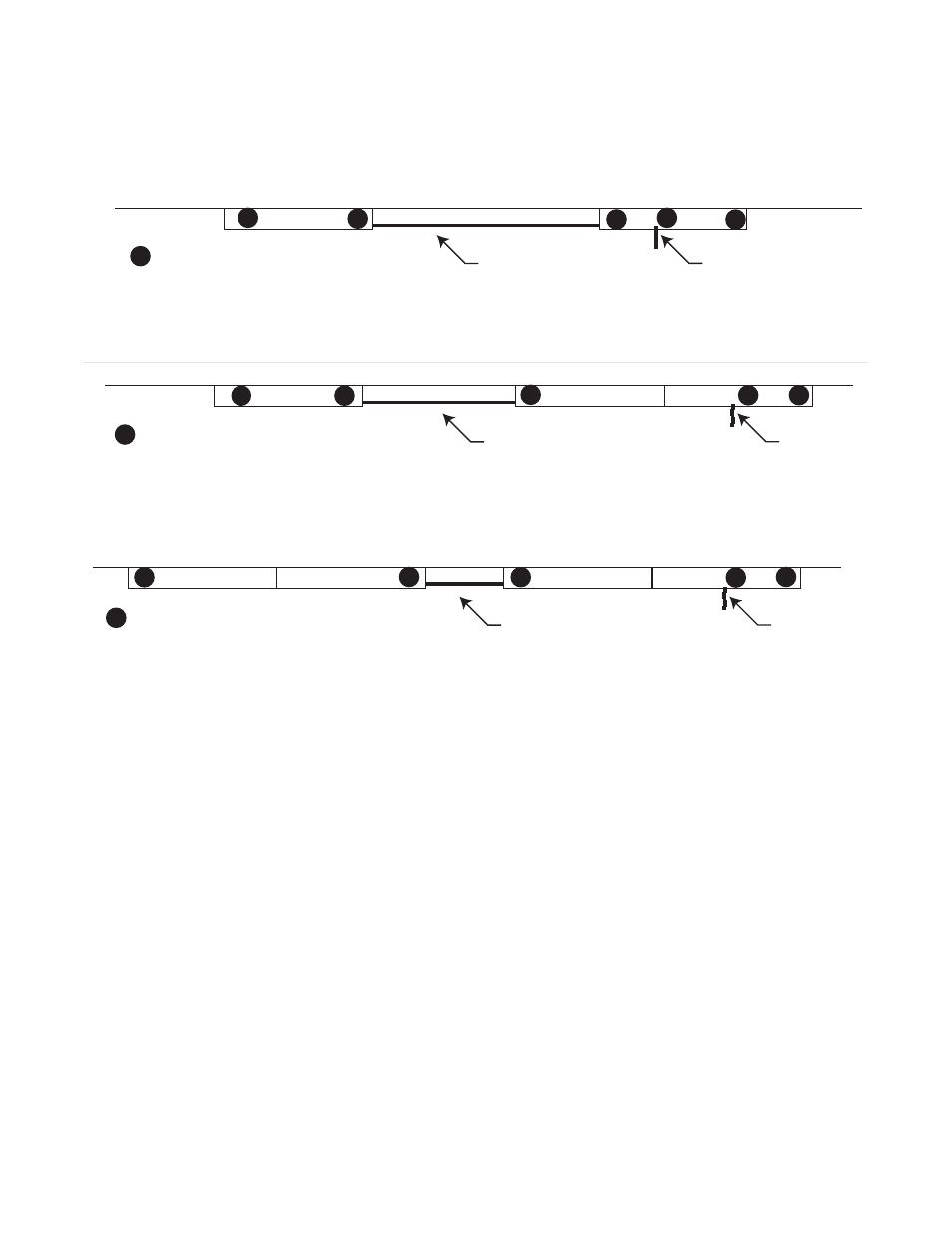
The following drawing shows correct placement of ground rods.
Above example #3: Double / Double
1: Clean all ground rod end(s) with abrasive to assure a good electrical connection. Keep all
ground straps untwisted, clear of standing water, with a drip loop, and as short as possible.
Secure the strap to the ground rods with the provided clamp and coat with grease.
Cover the connections to protect from condensation.
2: Connections to the weighbridge are installed by bolting to the provided bracket at the end
of each Scale Module. Scrape / sand enough paint / coating away to make a good electrical
connection, and coat with grease AFTER the connection has been made.
3: Ground rod #5 should be located near the interface conduit. It is used to connect to the
isolated ground of the Pit Power Supply (PPS) Acc 2001-1 only.
4: #1, ,2, 3, 4, and 5 Ground Rods are provided. These should be installed and correctly
connected with ground braid to the Anti-creep assy's with the provided hardware. Refer to
illustrations 50614_5, 50614_6, and Appendix VII. Ground rod connections 6, 7, and 8 are
not shown and are not provided by Fairbanks. Refer to 2-K: Grounding on page 30 for further
details.
2
1
3
4
5
Conduit
Instrument
Conduit to
= Ground Rod
X
between Modules
Single Module
Single Module
50614_8 A
1
4
5
Conduit
Instrument
Conduit to
= Ground Rod
X
between Modules
Single Module
Double Module
50614_9 A
2
3
Above example #1: Single / Single
Above example #2: Single / Double
Conduit
Instrument
Conduit to
= Ground Rod
X
between Modules
Double Module
Double Module
50614_10 A
1
4
5
2
3