1 main power board – E-Mon E50-6003200R*KIT User Manual
Page 6
CLASS 5000 METER
62-0392-03
6
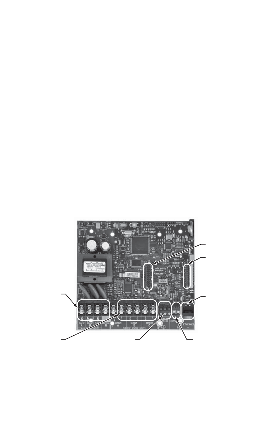
2.1 Main Power Board
Connections to this board include the MAIN Power Input and current sensors. The
MAIN Power Input terminals are positions one through four on the four position screw
terminal block, TB1. These terminals are covered with a protective shield for safety
purposes. The current sensor assemblies interface to the TB2, TB3 and TB4. Each
terminal block corresponds to an input voltage phase; care must be exercised to
ensure that each current sensor is connected to the correct terminal block. One three
terminal screw connector(TB42) is provided for RS-485 communications. One RJ-45
jack (J8) is provided for 10/100-base T Ethernet.
The contact is a solid-state switch for the phase-loss alarm function. Switching is
limited to 100 ma (0.1 amp) and voltage should not exceed 60 Volts AC or DC.
The (N.O.) contact closes within the meter due to the loss any one of the three lines of
voltage inputs to the meter. The contact closure may be used to activate an audible
alarm, light, control coil, or other indicator device. This alerts appropriate personnel to
the loss of voltage. An emergency phone dialer may also be programmed to send
notification automatically by phone, text, or pager. Alarming devices to be supplied by
others and are not included by with the E-Mon Class 5000 meter.
One two terminal screw connector provides phase loss alarming.
There are also two headers present for adding option cards. Header J3 is 20 positions
for use with an I/O board with up to two relays, two pulse inputs and two pulse out puts.
Header J4 is a 10 positions for use with modem and LonWorks TP/FT-10.
Fig. 2. Main Power Board.
M33271
TB1
POSITIONS
POSITIONS
6-10
PHASE LOSS
TB42
J3
J4
J8
- E50-6001600R*KIT E50-600800-R*KIT E50-600400-R*KIT E50-600200-R*KIT E50-600100-R*KIT E50-4803200R*KIT E50-4801600R*KIT E50-480800-R*KIT E50-480400-R*KIT E50-480200-R*KIT E50-480100-R*KIT E50-4003200R*KIT E50-4001600R*KIT E50-400800-R*KIT E50-400400-R*KIT E50-400200-R*KIT E50-400100-R*KIT E50-2083200R*KIT E50-2081600R*KIT E50-208800-R*KIT E50-208400-R*KIT E50-208200-R*KIT E50-208100-R*KIT