13 ethernet communications – E-Mon E50-6003200R*KIT User Manual
Page 33
CLASS 5000 METER
33
62-0392-03
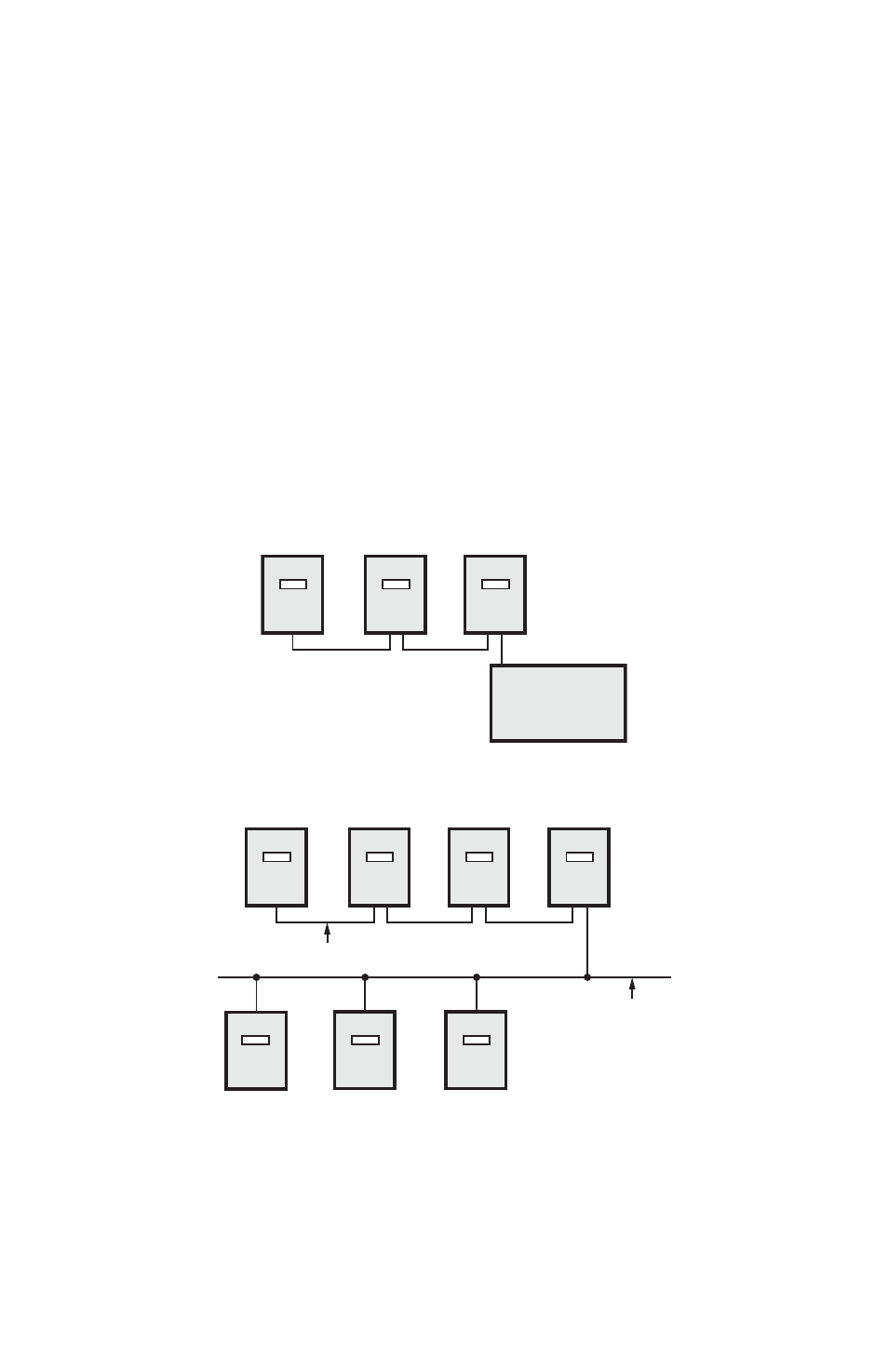
6.13 Ethernet Communications
Ethernet/IP communications connections are provided through an RJ-45
connector(J8) in the lower right corner of the main power board. This port can be
connected directly to a network port of a PC using a Cat. 5e crossover cable.
Two LEDs are provided directly above the connector. The LINK LED is yellow and
when lit, indicates ethernet connectivity. The ACT led is green and when lit, indicates
communication activity. The communication protocol for the Ethernet port is selected
when ordering the meter. The available choices are EZ7, Modbus TCP/IP and BACnet
IP. See the ordering information for the available choices in combination with the RS-
485 output.
Class 5000 Ethernet/IP Addressable meters can be tied into a local Ethernet network
individually, or a single Ethernet-connected meter can communicate with multiple RS-
485 daisy-chained conventional class 5000 meters using a single IP address. Each
device that is connected directly to the ethernet network requires a unique IP address.
SEE SECTION 10 FOR INSTRUCTIONS ON CHANGING ID AND IP ADDRESSES.
Fig. 18. Ethernet/IP Communications.
M32786
EMS OR
CONTROL UNIT
WITH MODBUS
COMMUNICATION
M32787
ETHERNET
NETWORK
RS-485 DAISY CHAIN (SECTION 5.7)
- E50-6001600R*KIT E50-600800-R*KIT E50-600400-R*KIT E50-600200-R*KIT E50-600100-R*KIT E50-4803200R*KIT E50-4801600R*KIT E50-480800-R*KIT E50-480400-R*KIT E50-480200-R*KIT E50-480100-R*KIT E50-4003200R*KIT E50-4001600R*KIT E50-400800-R*KIT E50-400400-R*KIT E50-400200-R*KIT E50-400100-R*KIT E50-2083200R*KIT E50-2081600R*KIT E50-208800-R*KIT E50-208400-R*KIT E50-208200-R*KIT E50-208100-R*KIT