Teledyne 3010MA - Paramagnetic oxygen analyzer, includes 0-100% range User Manual
Page 70
Part 2 Analysis Unit
Model 3010MA
70
Teledyne Analytical Instruments
The Paramagnetic sensor and heating elements are contained within
the Analysis Unit but the temperature controller, sensor electronics,
preamplifier and compensation circuitry are located in the Control Unit
and interfaced to the Analysis Unit via the rear panel cable connections.
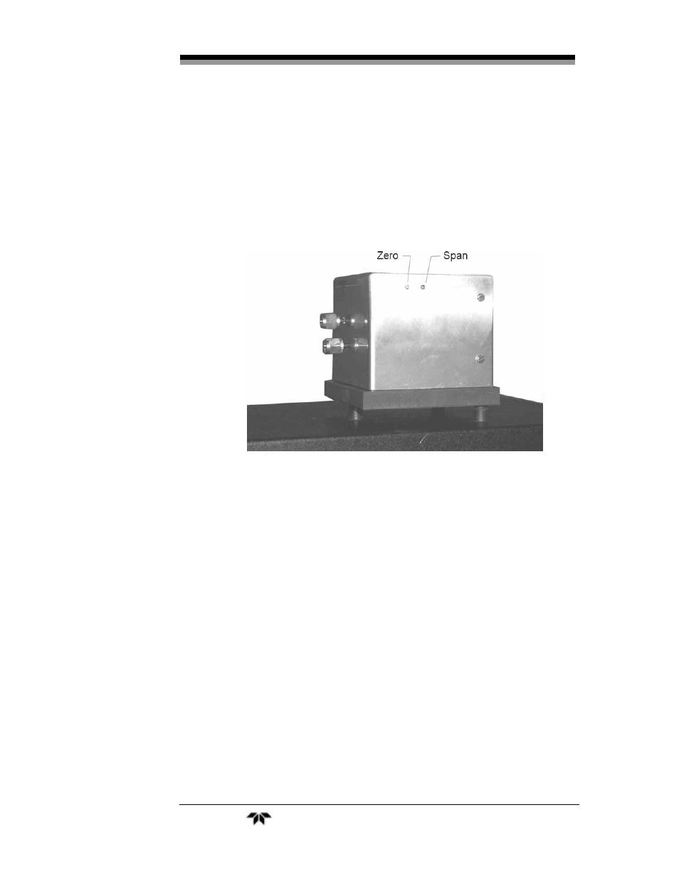
Figure 6-1 is a drawing showing the front view of the paramagnetic
sensor. Note the location of the Zero and Span adjustments on the upper
left side of the sensor. Figure 6-2 is a drawing showing the side of the
sensor. Figure 6-3 shows the actual sensor and the location of the zero and
span trimpots.
Figure 6-3: Sensor and Trimpot Identification
The electrical interconnections to the sensor are done through a 15-
pin D-Sub connector. Some signals from the sensor are not connected.
They are only useful for troubleshooting, by trained personnel, as test
points. A separate cable is used for heating element power. Table 6-1
indicates the pin connections within the sensor cable while Figure 6-4
shows the sensor cable and identifies the pin locations.
Table 6-1: Sensor Cable Pin Configuration
Pin #
Description
1 -15Vdc test pin (Not connected)
2 +15Vdc test pin (Not connected)
3 Measuring
ground