Teledyne 3010MA - Paramagnetic oxygen analyzer, includes 0-100% range User Manual
Page 36
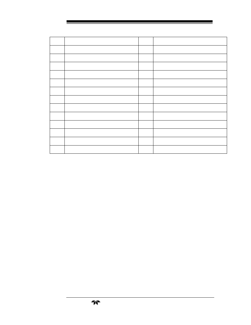
Part 1 Control Unit
Model 3010MA
36
Teledyne Analytical Instruments
12
(-) Remote Span
37
System Alarm, NO Contact
13
38
Range 1 ID Contact
14
39
Range 2 ID Contact
15
Remote ZERO valve (return)
40
Cal Contact
16
Remote SPAN valve (return)
41
Cal Contact
17
Remote SPAN valve (hot)
42
18
Range 3 ID Contact
43
19
Range 3 ID Contact
44
20
System Alarm Moving Contact
45
21
Range 1 ID Contact
46
22
Range 2 ID Contact
47
23
(-) Range ID, 0-1VDC neg gnd
48
Remote EXHAUST valve (return)
24
(+) % Range, 0-1VDC
49
Remote ZERO valve (hot)
25
50
Remote SAMPLE valve (return)
* Available by special option only.
3.3.2.4
RS-232
P
ORT
The digital signal output is a standard RS-232 serial communications
port used to connect the analyzer to a computer, terminal, or other digital
device. It requires a standard 9-pin D connector.
The data is status information, in digital form, updated every two
seconds. Status is reported in the following order:
The concentration in percent
The range in use (HI, MED, LO)
The span of the range (95-100%, etc)
Which alarms—if any—are disabled (AL–x DISABLED)
Which alarms—if any—are tripped (AL–x ON).
Each status output is followed by a carriage return and line feed.
Four input functions using RS-232 have been implemented to date.
They are described in Table 3-1.