Thermal-controlled vacuum-switching valves, Electrical /vacuum solenoid – Mityvac MV8500 silverline elite aUtoMotive test kit User Manual
Page 18
SERVICE PROCEDURES
These control valves are called Ported Vacuum
Switches (PVS) when used on Ford engines . Thermal
Ignition Control (TIC) valves when used on Chrysler
products, and Distributor Thermal Vacuum-Switches
(DTVS) when used on General Motors engines .
The two-port valve is used to stop EGR while the
engine is cold . This type of thermal switch is needed
to provide good drivability by limiting the entrance
of EGR until the engine is warmed up .
The three-port valve is commonly called a cooling
system PVS because it switches the vacuum source to
the distributor from ported to full intake vacuum .
The four-port valve has been used in some Ford
engines to bypass the spark delay valve and cut
out the EGR system when the engine is cold .
SERVICE PROCEDURES
Follow this procedure to test the two-port
vacuum-switching valve:
1) Apply 10” Hg of vacuum to the bottom port of
the valve with your vacuum pump and measure the
results with a second vacuum gauge as shown in the
accompanying illustration (FIGURE 15) .
) The valves are color-coded and the green valve
should open and pass vacuum at 68°F, the black
valve at 100°F .
thermaL-controLLeD vacuum-switchinG vaLves
SERVICE PROCEDURES
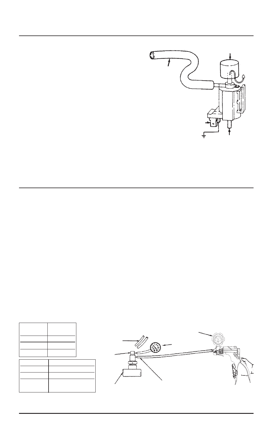
1) Disconnect vacuum and electrical connectors from
the solenoid . Connect the pump to port “B” and
attempt to apply vacuum with pump . Vacuum
should be released through port “A” (FIGURE 14) .
) Using jumper wires, connect negative solenoid
terminal to ground and apply 1 volts to the
positive terminal . Apply vacuum to port “B” .
Vacuum should hold and not bleed off . If the
solenoid does not hold vacuum, replace solenoid .
3) With solenoid still energized, move vacuum
pump to port “A” . Attempt to apply vacuum .
Vacuum should be released through the air filter
and no vacuum should be present at port “B” .
eLectricaL /vacuum soLenoiD
FIGURE 14: TYPICAL VACUUM SOLENOID
Air Filter
Port “A”
Positive Terminal
Port “B”
FIGURE 15: TESTING THE TWO-PORT PVS
1) Remove both hoses
from valve
Color code
) Connect a vacuum gauge
to one port and a remote
vacuum supply to the other
4) Operate the engine
until the coolant warms
above the valve setting (see table)
3) Apply 10 inches
vacuum to the valve
5) See if there is a
vacuum reading on
this gauge
RESULTS:
No Vacuum
Replace the PVS valve
Vacuum
PVS valve is open
Vacuum when Replace the
coolant is cold PVS valve
Color
Coolant Above
Code
Temperature
Green
68°F
Black
100°F
Plain or Blue
133°F
Page Number - 18
Form 8433