Exhaust gas recirculation (egr) – Mityvac MV8500 silverline elite aUtoMotive test kit User Manual
Page 16
EGR VENTURI VACUUM AMPLIFIER
Some engines utilize a Venturi Vacuum Amplifier
that uses the weak vacuum signal from the throat of
the carburetor to allow the passage of the stronger
intake manifold vacuum to operate the EGR valve .
On most applications the amplifier provides a ” Hg
boost to the Venturi signal (FIGURE 10) .
SERVICE PROCEDURES
1) Start the engine, and run it at idle until it reaches
normal operating temperature .
) Make sure the intake manifold hose to the
amplifier is properly connected . On those systems
with a reservoir, remove the hose from the reser-
voir and use a tee connector to join the hose to the
intake manifold vacuum hose .
3) With separate lengths of hose and different
connectors, bypass any and all vacuum valves or
coolant controlled valves between the amplifier
and the EGR valve .
4) Use a tee connector to attach the pump into the
vacuum line between the amplifier and EGR valve .
5) Increase engine speed to 1500 to 000 RPM
and release the throttle . Let the engine return to
idle speed and remove the vacuum hose at the
carburetor venturi . The vacuum reading should be
within ± 0 .3” Hg of the specified boost for that
amplifier if other than zero boost is specified .
Zero boost may read from 0 to .5” Hg . Replace
amplifier if it is out of specification .
6) Increase engine speed . Watching the vacuum
gauge, release the accelerator after a speed of
1500 to 000 RPM is reached . If the vacuum gauge
reading shows an increase greater than 1” Hg
during acceleration period, the amplifier should
be replaced .
7) Remove the pump from the output vacuum
line and reconnect the hoses, but still bypass other
valves . Connect the pump and apply to 4” Hg of
vacuum to port on the amplifier which is normally
connected to intake manifold vacuum . The EGR
valve should operate and engine idle should drop or
become erratic . If the EGR valve fails to move,
replace the amplifier .
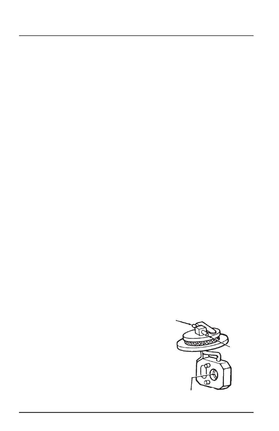
BACK-PRESSURE TRANSDUCER VALVE
(BPV) OPERATION
The Back-pressure Transducer Valve (BPV) controls
the amount of EGR according to the load on the
engine . An exhaust pressure probe extends into
the exhaust crossover passageway to sample the
exhaust gas pressure . During light engine loads,
the pressure in the exhaust passageway is relatively
low, while during wide-open throttle operation
(WOT), the pressure is highest . This pressure signal
is transmitted to a diaphragm in the BPV and is used
to control the amount of vacuum applied to the EGR
valve (FIGURE 11) .
SERVICE PROCEDURES
1) Remove the air cleaner and plug the intake
manifold fitting . Start the engine and bring it to
normal operating temperature . Position the fast-idle
cam follower on the second step of the fast-idle cam
(to obtain about 1500 RPM), and then note engine
speed on a tachometer . Use the pump to check the
source vacuum at an intake manifold port (FIGURE
1) . Note this reading .
) Tee your pump into the vacuum passageway to
the BPV and the reading should be 1 to ” Hg of
vacuum . Replace the BPV if it is not within specifica-
tions .
3) Leave the vacuum gauge at this location, remove
the hose to the EGR valve, and plug the hose open-
ing . Read the vacuum pump gauge, which should be
the same as the intake manifold vacuum reading . If
it is not within ” Hg of the source vacuum, replace
the BPV valve .
eXhaust Gas recircuLation (eGr)
FIGURE 11:
EXHAUST BACKPRESSURE TRANSDUCER VALVE
To Distributor
Spark–
EGR Thermal
Vacuum Valve
Exposed to Exhaust Gas Pressure
To EGR
Valve
Page Number - 16
Form 8433