Hhy yf fiir re e 6 6a a – Mallory Ignition Mallory HYFIRE 6A and 6AL SERIES ELECTRONIC IGNITION CONTROLS 6852M_6853M User Manual
Page 12
®
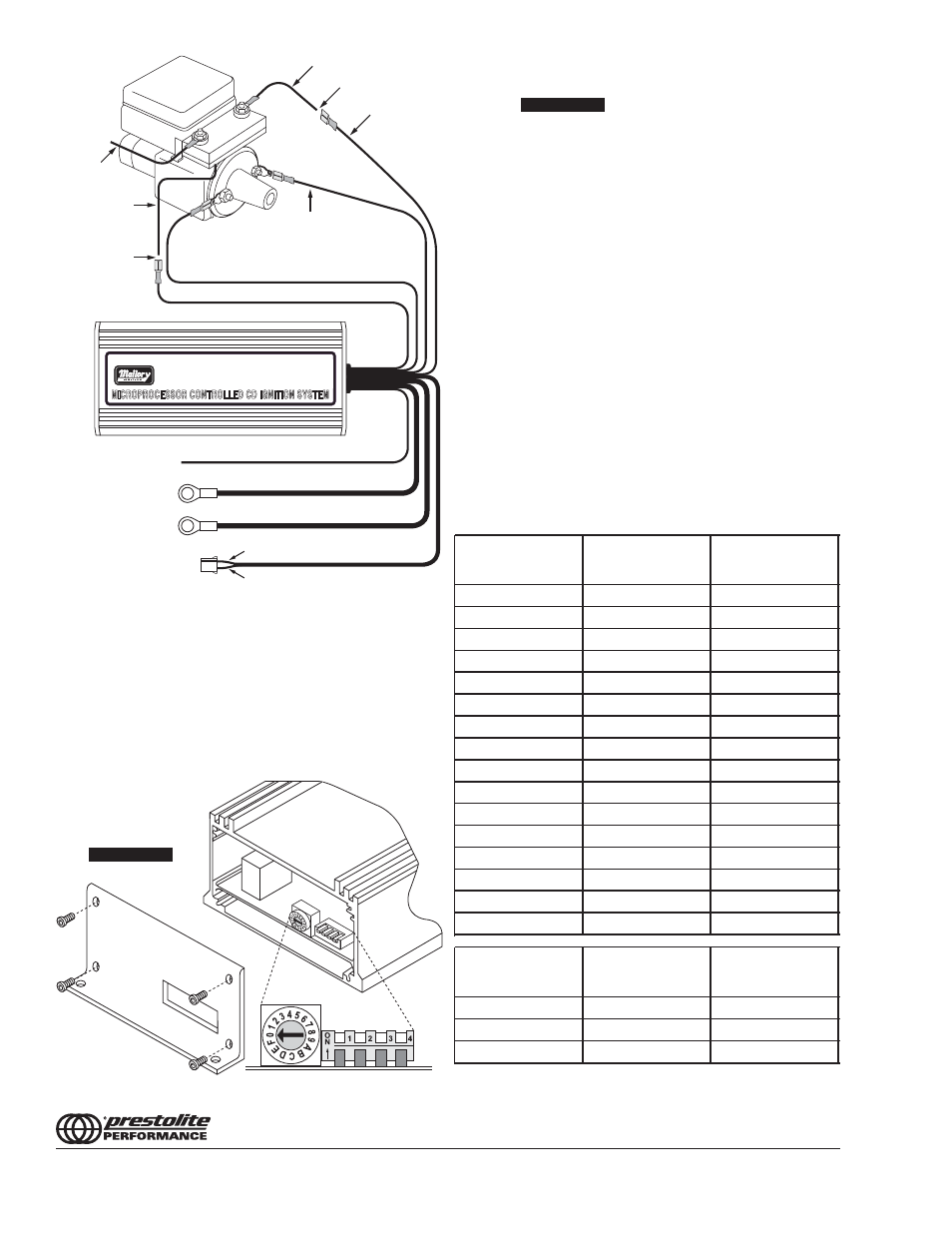
PART No. 6852
R
YELLOW
TO TACHOMETER
RED (LARGE 14 GA)
TO BATTERY POS (+)
BLACK (LARGE 14 GA)
TO BATTERY NEG (-)
GREEN
PURPLE
RED (SMALL 18 GA)
MAGNETIC PICKUP
NOT USED
ORIGINAL COIL (+) WIRE
SPLICE HERE
WHITE
(-) BLACK (SMALL 18 GA)
AMPLIFIER
ORIGINAL COIL (-)
TERMINAL FROM
AMPLIFIER
TO IGNITION
SWITCH
(+) ORANGE
SPLICE HERE
MALLORY IGNITION
www.malloryperformance.com
12
Installing the HYFIRE
®
6A with
a Typical Import Application
FORM 1522TL
Made in U.S.A.
Printed in U.S.A.
MALLORY IS A DIVISION OF PRESTOLITE PERFORMANCE
(216) 688-8300
RPM LIMITER SETTINGS
Note the sticker attached to the end plate of the HYFIRE
®
6-AL.
This sticker shows settings for number of cylinders and RPM
limits. In case the sticker becomes damaged or otherwise
unreadable, the settings are shown at right.
Setting Switch #4
This switch must remain in the down position for normal
operation. CAUTION: Using the Mallory HYFIRE
®
6-AL (6AL) with
switch #4 in the up position could cause ignition damage.
Rotary Switch
Switch #1
Switch #1
Position
DOWN
UP
0
4,500
8,500
1
4,750
8,750
2
5,000
9,000
3
5,250
9,250
4
5,500
9,500
5
5,750
9,750
6
6,000
10,000
7
6,250
10,250
8
6,500
10,500
9
6,750
10,750
A
7,000
11,000
B
7,250
11,250
C
7,500
11,500
D
7,750
11,750
E
8,000
12,000
F
8,250
NO LIMIT
Number of
Cylinders
Switch #2
Switch #3
4
UP
Down
6
Down
UP
8
Down
Down
FIGURE 22
FIGURE 23
H
HY
YF
FIIR
RE
E 6
6A
A