Luminex IS Version 2.3 User Manual
Page 74
Luminex IS Software Manual for Version 2.3
x
MAP Technology
64
PN 89-00002-00-110 Rev. B
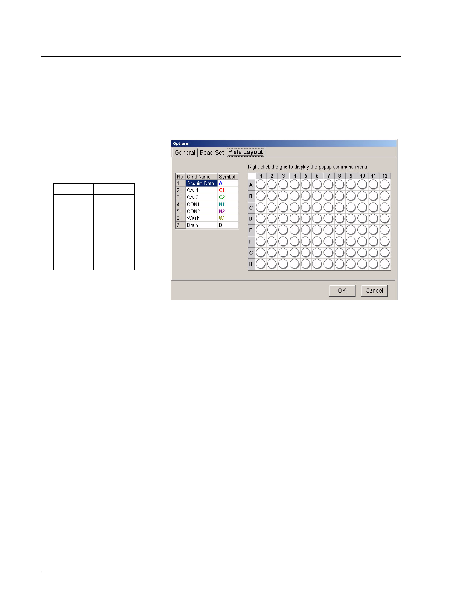
8. Click the Plate Layout tab. See Figure 37. On this tab you
define commands for the desired wells on the plate. You can
define commands that apply to one or more wells, one or more
rows of wells, or one or more columns of wells. You can define
on-plate or off-plate commands.
Figure 37 Plate Layout Tab
9. Select wells. To select a single well, click the well. To select
multiple wells in a group, click and hold the mouse button with
the cursor over the first well, then drag the cursor around the
desired wells. To select a row or column click the letter or
number of the row or column.
10. Select plate commands. Right-click over the selected wells to
display the Command menu. See Figure 38. Select the desired
command. The associated command symbol appears in the
designated plate well. To make a correction, select the wells
(selected wells are outlined in blue), right-click over the selected
wells to display the Command menu, and then click Clear
Selection from the list. Table 10 (following) lists Plate Layout
selection shortcuts.
Table 9. Symbol
Color Codes
Symbol
Color
A
C1
C2
N1
N2
W
D
S
Blue
Red
Green
Teal
Purple
Olive
Black
Fuchsia
Note:
The legend at the left side
of the tab (No, Cmd Name, and
Symbol columns) shows available
commands and their colored-
coded symbols. Symbol appears
in the well when selected from
the Command Menu.
Note:
Wells are always read in
rows (letters A to H) and columns
(numbers 1 to 12) starting with
A1. If partial columns are
selected they are still read in the
same order. Unselected wells are
skipped.