Step 1 hinge mount tube installation, Step 2 hinge mount tube installation, Pull to open installation top view) – Controlled Products Systems Group PAT1AC User Manual
Page 8
6
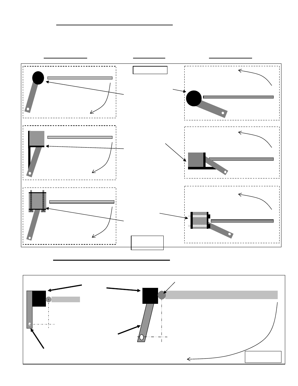
STEP 1 Hinge Mount Tube Installation
Use the diagrams in Figure 1 below to determine the type of installation and gatepost required. These
diagrams show left hand installation - reverse for right hand installation. Figures 2 and 3 show installation
for thick wall posts.
PULL TO OPEN
POST TYPE
PUSH TO OPEN
STEP 2 Hinge Mount Tube Installation
(Pull to Open Installation Top View)
Use dimensions in figure 2 to determine mounting location of Hinge mount tube, cut hinge mount tube as
necessary to achieve correct mounting dimension. Option 1 offers maximum strength.
GATE IN CLOSED POSITION
Thin wall steel post.
Add support to
prevent twisting.
Support not needed if
using thick wall post
as shown in Figure 2.
GATE IN CLOSED POSITION
4” round steel post.
Saddle cut tube to fit.
Wood post
add metal plate
bolt on with
½ inch Carriage
bolts/washers/nuts.
GATE IN CLOSED POSITION
OPEN DIRECTION
OPEN DIRECTION
OPEN DIRECTION
OPEN DIRECTION
GATE IN CLOSED POSITION
GATE IN CLOSED POSITION
GATE IN CLOSED POSITION
OPEN DIRECTION
OPEN DIRECTION
FIGURE 1
Hinge mount tube cut as necessary to
achieve dimension needed.
Must be level in all directions for proper
alignment and operation.
Figure 2
B
13”
A
6”
Option 1
GATE
Option 2
Gate post 4” steel shown
¼” wall.
B
13”
A
6”
For 90 degree opening 6” and 13” as shown
For 100 degree opening 7 1/2” and 12”
For 110 degree opening 9” and 10 1/2”
For 120 degree opening 11” and 8”
GATE
OPEN DIRECTION
HINGE
Figure 1