Step 8 installation of charging device, Solar panel and solar charge controller, Mount panel facing southwest – Controlled Products Systems Group PAT1AC User Manual
Page 13: Ac charger
11
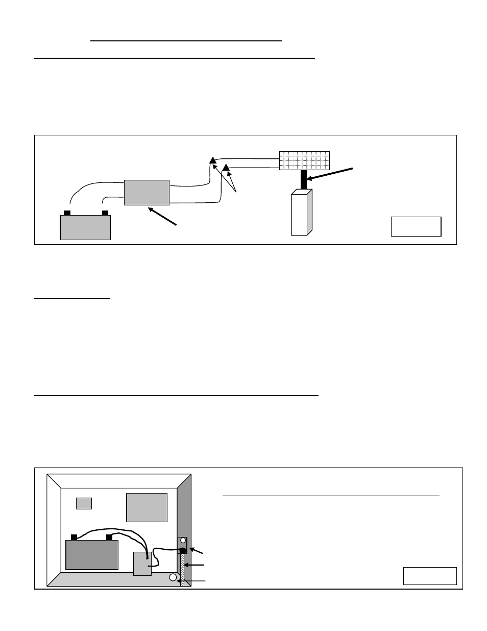
STEP 8 Installation of Charging Device
SOLAR PANEL AND SOLAR CHARGE CONTROLLER
Locate and mount the solar panel bracket so that the panel faces southwest and maintains the preformed
45-degree angle. The standard cable is 15' in length and must feed in through the bottom of the control box.
Pay attention to the distance when determining your mounting location. Although the cable can be extended
with watertight connectors, charging power is diminished. Sometimes it is necessary to locate the panel
farther away to achieve optimum sunlight, but consider that optimum sunlight might not mean optimum
charging if the distance is too great. Use #16 gauge wire or larger and keep length as short as possible.
WIRING DIAGRAM
Mount panel facing
Southwest.
Note: Avoid shaded areas if possible. Panels should face southwest for optimum
charging. See explanation above for details.
AC CHARGER
Locate and install the AC battery charger inside the control box. The charger requires a receptacle for 110-
volt AC supply. The recommended location is inside the control box. A licensed electrician should install the
receptacle per local building codes
Modifying the charger power cord will void the charger warranty.
Note: USAutomatic recommends an AC surge protector on all 110-volt AC installations,
especially in lightning prone areas. Do not modify the AC cord on the charger.
Connecting Actuator Cable and Charging Device to Battery
(solar panel or AC charger)
Connect the charging device (solar charge controller or AC charger) ring terminals and the actuator cable
ring terminals to the battery (red to + and black to -). Patriot II installations have 2 sets of actuator ring
terminals to connect.
Connect the charger power cord to the 110-volt AC receptacle. The red light on the charger should come on
and the yellow light should begin to blink. If the red light does not come on, check the 110-volt AC power.
Receiver
Do not connect actuator cable to the control board at this time..
Control
Board
JUNCTION BOX MOUNTED INSIDE CABINET
CONDUIT
INSTALL SNAP IN GROMMET TO PROTECT WIRES.
Assemble panel to bracket
with supplied hardware.
Figure 13
Yellow Lead
Positive +
Negative -
Battery
Red Lead
Black Lead
Wire Charge Controller in
series between solar panel
and battery.
Black Lead
Red Lead
Black Lead
Charge
Controller
Wire
Nuts
Figure 14
+ -
Battery
Charger