Step 4 gate bracket installation, Step 4a gate bracket installation, Step 4b gate bracket installation – Controlled Products Systems Group PAT1AC User Manual
Page 10
8
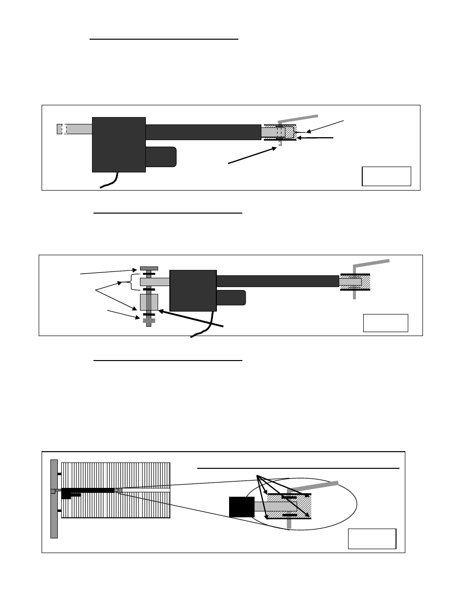
STEP 4 Gate Bracket Installation
(Prepare Actuator for Installation)
NOTE:
Do not operate the actuator before performing all installation steps. There is no need to
extend the actuator before all installation steps are complete. If you must operate the
actuator, ensure that the extension screw does not rotate while operating to avoid possible
actuator damage.
Assemble the Gate bracket to the actuator as shown in figure 5.
STEP 4a Gate Bracket Installation
(Installing the actuator)
Mount the actuator to the hinge mount tube as shown in Figure 6.
The actuator can be installed upside down at this point to make limit switch adjustments needed later easier to
access. Remember to flip actuator back to position shown in figure 6 after all adjustments are made.
STEP 4b Gate Bracket Installation
(PULL to Open Only)
The actuator is adjusted to the fully retracted or open position from the factory. Once the actuator is
connected to the hinge mount tube, swing the gate to the desired open position and block in place to secure
the gate. Move the actuator around so that the gate bracket can be attached to the gate. Ensure the gate is in
the fully open position.
Clamp the gate bracket to the gate (verify actuator is level before welding). Be sure that your gate does not
move while clamping. The location of the gate will set your open position. The actuator cylinder will be
level if all steps were performed accurately. Weld gate bracket to the gate and verify actuator is still level.
4 ½” bolt
3 – ½” washers
½” self locking nut
Figure 6
Hinge mount tube
½ inch Manual Release Pin
2- ½” washers
Gate
Bracket
Figure 5
Install clip to hold manual
release pin in place.
GATE SECURED IN DESIRED OPEN POSITION
Weld while clamped
Figure 7