3 dip-switch settings 7.2 dc system description, Wiring dual operators in manual mode, Switch function setting description – Controlled Products Systems Group 9150-080 User Manual
Page 42
9150-065-S-9-11
40
DC Motor Negative Output
DC Motor Positive Output
Batter
y Negative Input
Batter
y Positive Input
24 V
AC Common
24 V
AC Input
Activation Output
Radio Power
Open Input
Common
7.3 DIP-Switch Settings
7.2 DC System Description
Switch
Function
Setting
Description
Power Failure
Operating Modes
Restored
AC Power
Operator
Response
OFF
ON
OFF
OFF
Operator Type
Manual input from 2340 board needed to open gate when a power outage occurs.
Do Not
Adjust
Do Not Adjust DC Timer needs
to be adjusted.
Charging LED
Not Used
1
2
3
4
5-8
Gate will automatically open when a power outage occurs.
OFF
ON
When AC power is restored, a manual input (push button, loop, radio receiver, etc.)
is required to return the gate to normal operation from 2340 or 4602 board.
When AC power is restored, a 1-second pulse is sent to the gate operator input to
automatically restore normal operation.
Must be in the OFF position for the 9150.
Must be in the OFF position.
2340
Gate will automatically OR be manually OPENED and
STAY open during an AC power failure. DIP-Switch 3
setting will determine how operator will return to
normal operation once AC power has been restored.
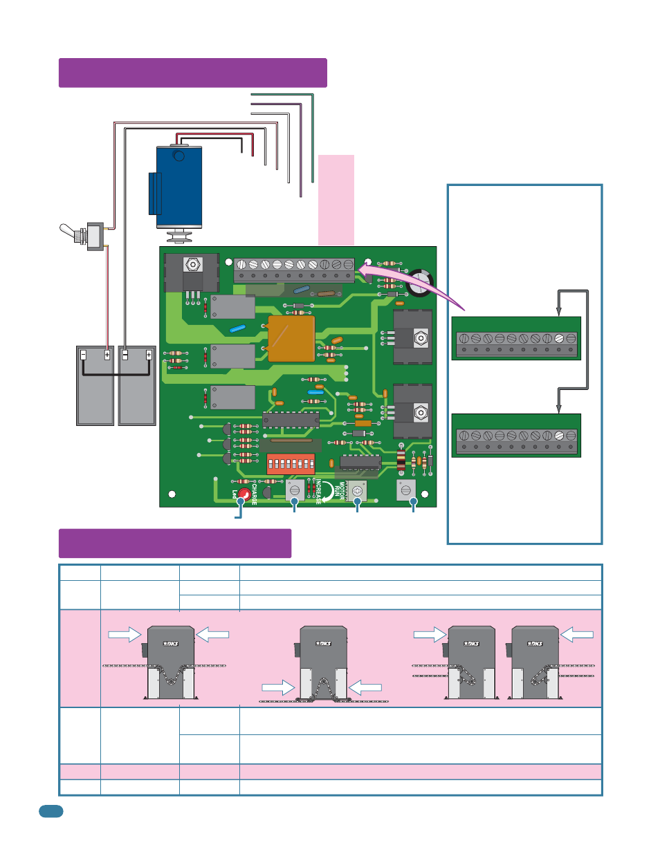
If the operators will be in Manual
mode (Switch 1 OFF) to OPEN the
gates after an AC power failure,
connect terminal #2 on each of
the 2340 boards together.
This wiring will NOT affect the
Auto mode function if the
operators are switched from
Manual mode (Switch 1 OFF) to
Auto mode (Switch 1 ON) in the
future.
Primary Operator
2340 Board Terminal
DC
ON/OFF
Power
Switch
Inter
connection Cable Wire
Red/White
Red/White
DC Motor
Green to 4602 Main Terminal #4
Purple to 4602 Main Terminal #3
White to 4602 Main Terminal #18
Secondary Operator
2340 Board Terminal
See
previous
page.
DIP-Switches
2340 Board Terminal
DC Timer
Wiring DUAL operators
in Manual Mode.
Black/White
Batteries
12 V
3 Amp/Hr
Battery
12 V
3 Amp/Hr
Battery
8 7 6 5 4 3 2 1
ON
10 9 8 7 6 5 4 3 2 1
10 9 8 7 6 5 4 3
2
1
10 9 8 7 6 5 4 3
2
1
Gray
Opening Direction. Setting must be the same as SW 1, switch 1 on the 4602 circuit board.
Opening
direction
using OFF
setting.
Opening
direction
using ON
setting.
Opens
with
ON
setting.
Mounts
Right
All Rear
Opens
with
OFF
setting.
Opening
direction
using ON
setting.
Opening
direction
using OFF
setting.
Mount
Front
Post
Mounts
Center or
Mounts
Left
All Rear