3 auxiliary device wiring – Controlled Products Systems Group 9150-080 User Manual
Page 35
9150-065-S-9-11
33
KEY SWITCH
4602
NC
NO
18
17
16
15
14
13
12
11
10
9
8
7
6
5
4
3
2
1
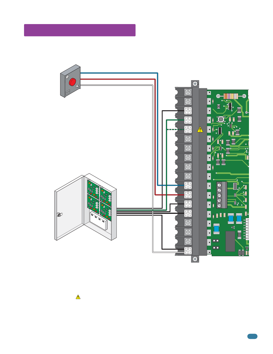
5.3 Auxiliary Device Wiring
Gate Tracker
(Quad Box Shown)
Remote Alarm Reset Station
(DoorKing P/N 1404-080 Only)
MUST be mounted in the
line-of-sight of the gate operator.
Red Alarm Output Terminal
Blue Alarm Reset Terminal
White Common Terminal
DoorKing Access Control System (Model 1833, 1835, 1837 or 1838)
tracker system can be connected.This system can keep track of gate
operator
cycle count, shorted inputs, loop detector problems, any forced entry
attempts, if the gate has struck anything during the open or close cycle,
power interruptions, etc.
For more detailed information refer to the Tracker Installation and Wiring
Manual, DoorKing P/N 2351-010.
Terminal #4 (Full open) or #5 (14-Ft. open) required only if the tracker
board will activate the gate operator. Refer to the manual 2351-065 for
detailed information.