Dc timer – Controlled Products Systems Group 9150-080 User Manual
Page 41
9150-065-S-9-11
39
SECTION 7 - OPTIONAL CONVENIENCE OPEN ADJUSTMENTS
The optional convenience open system installed in your vehicular gate operator is designed as a convenience enhancement only.
It is not designed or intended to provide continuous gate operation during a power outage. Its sole purpose is to provide a
method to open the vehicular gate to allow unimpeded traffic flow when the gate and access control system is without power. If
your access control system requires 100% power backup and continuous operation when primary (AC) power has failed, a
power inverter / backup system, such as DoorKing’s Model 2000, is required.
•
The convenience open system cannot provide continuous gate operation during a power outage.
•
The gate will cycle (Manual or Automatic Mode) to the open position ONE TIME ONLY after AC power failure.
•
The convenience open system requires testing on a monthly basis to insure the batteries are fully charged and that the
system is operational.
•
The convenience open system uses two 12-volt, 3.0 amp-hour gel-cell batteries. These batteries should be replaced
every two years on average, or sooner if required.
•
Batteries are affected by temperature. Cold temperatures will reduce the effectiveness of the batteries. High temperatures
will result in a shortened battery life.
•
Batteries are not covered under warranty.
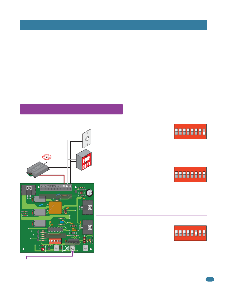
7.1 Circuit Board (2340) Setup
The Convenience Open system will automatically
open the gate approximately 3 seconds after loss
of AC power. The DC timer will run the DC motor.
NO devices need to be connected to the 2340
board. Automatic mode is always used for gates in general access
applications such as gated communities, apartment complexes, etc.
The system will NOT automatically open the gate
after loss of AC power. A manual input is needed
(Remote, push button or a key switch) to open
the gate from one of the “Manual Mode Devices”
physically wired to the 2340 circuit board (The DC timer will run the DC
motor). Any control devices wired to the 4602 main terminal will NOT
function after loss of AC power.
Note: If the gate operator is controlled by a DoorKing access controller
(Models 1833, 1835, 1837 or 1838), the “Manual Mode” will NOT function
during a power outage.
DC Timer:
MUST be adjusted so the gate stops approximately six inches from the full open position. Clockwise increases
the DC motor run time, counter-clockwise decreases the run time. Do not allow the DC motor to run long enough to hit the
gate stop and continue to run. The operator clutch will slip and stall the DC motor. The circuit board may get damaged!
This radio receiver will work during
normal daily operation as well as
during a power outage. The radio
receiver will be powered from the
operator’s batteries during a power
outage.
Automatic Mode
after loss of AC Power, Switch 1 ON.
Manual Mode
after loss of AC Power, Switch 1 OFF,
Residential Use ONLY.
Manual Mode Device Connection
Once AC power is restored, the system’s control
board can be set to “automatically re-key” the
gate operator (switch 3 ON) to establish normal
operation, or can be set to require a “manual input” from the 2340 OR
4602 circuit board (switch 3 OFF) before the operator resumes normal
operation.
Restart Options
once AC Power is restored,
Switch 3 ON or OFF.
2340
Com
Relay
24 Volt
Stand-Alone Radio Receiver
Push
Button
Dry Contact
Emergency
Vehicle Access
Dry Contact
DIP-Switches
2340 Board Terminal
DC Timer
See next page for specific dual operator wiring.
8
10 9 8 7 6 5 4
3 2 1
7 6 5 4 3 2 1
ON
ON
N
1
2
3
4
5
6
7
8
ON
1
2
3
4
5
6
7
8
ON
1
2
3
4
5
6
7
8