2 control wiring for single/primary operator – Controlled Products Systems Group 9150-080 User Manual
Page 34
9150-065-S-9-11
32
KEY SWITCH
4602
NC
NO
18
17
16
15
14
13
12
11
10
9
8
7
6
5
4
3
2
1
“Optional” REVERSES GATE for
Closing Direction Photo Sensors
Functions ONLY during gate closing cycle.
SW 2, switch 2: After photo sensor beam
gets obstructed:
OFF Setting - REVERSES GATE.
ON Setting - Stops gate then continues
closing when gate is clear (Same function
as UL 325 terminal #2).
Note: The ON setting is used to help prevent tailgating
but the photo sensor should be wired to the UL 325
terminal #2 when the “stop gate” function is desired,
see page 28 for more information.
W
ARNING
MOVIN
G G
ATE
CAN
CA
USE
Op
era
te ga
te o
nly
w
hen
ga
te a
rea
is i
n s
igh
t
and
free
of pe
opl
e a
nd
ob
str
uc
tions
.
Do
not
allow
ch
ildr
en
to
pla
y in
ga
te a
rea
or
op
era
te ga
te.
Do
no
t sta
nd i
n ga
te p
ath
or
wa
lk th
roug
h
pa
th
whi
le ga
te is
mov
ing
.
Rea
d owne
r’s ma
nua
l and
sa
fety
ins
truc
tions
.
SER
IO
US
IN
JU
RY
OR
DEA
TH
CL
ASS
CE
RTIF
IED
TO
CAN
/CSA
C22
.2 N
O. 2
47
CO
NFO
RMS
TO
AN
SI/U
L-3
25
VE
HICULAR
GA
TE OPERA
TOR
HP
533
82
MO
DE
L
SER
IAL
VO
LTS
PH
ASE
AM
PS
60 H
z
MAX
G
ATE LO
AD
Door
Ki
ng,
Inc
., Ingl
ew
ood,
CA
ON
ON
REVER
SE
SENS
ITIVIT
Y
REV
ERS
E
LOOP
EX
IT
LOOP
KE
Y SWIT
CH
DOORK
IN
G
4602
-01
0
SW1
SW
2
OP
EN
TIM
ER
NC
1
2
3
4
5
NO
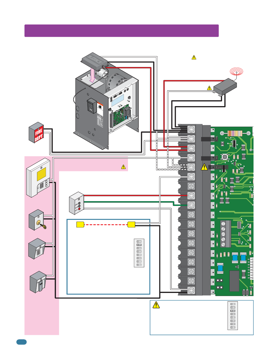
5.2 Control Wiring for Single/Primary Operator
ON
1
2
345678
SW 2
Red Full Open
Green Close
White Com
Key Switch
Stand-Alone
Keypad
Stand-Alone
Card Reader
Telephone
Entry
Fire Box
3-Button Control Station
DoorKing ONLY
Note:
All stand-alone and
telephone entry
devices must use a
separate power
source.
#4-Connected device fully opens gate.
#5-Connected device opens gate 14-feet.
#2-Full Open
Important:
Controls must be far enough from the gate so that the user is prevented from coming in contact with the gate while
operating the controls. Outdoor or easily accessible controls should have a security feature to prevent unauthorized use.
Com
Com
Com
Relay -
#2 - Full Open.
#5 - Opens gate 14-feet.
Relay N.O. - #2 - Full Open.
#5 - Opens gate 14-feet.
250 mamp.
max.
3-Wire Radio Receiver
ON
12
3
45678
SW 2
SW 2,
switch 3
must be
OFF.
Relay Com
24 Volt Com
24 Volt - 250 mamp. max.
4-Wire
Receiver
#5 Terminal Note (Single Operator Only):
Any opening device connected to terminal #5
will open the gate to the partial open 14-ft setting.
Secondary entrapment protection devices will also
open the gate to the partial open setting. If the
Inherent Reverse Sensor gets activated during the
close cycle, it will always fully open the gate.
24 volt
Full Open
Full Open
Partial Open
Wiring opening device when using
“Manual Mode Operation” for
convenience open operator(s):
The opening device should be wired
to the 2340 circuit board when
using the convenience open
system to “manually open”
the gate(s) during a power
failure. This will allow normal
daily operation as well as AC
power failure operation. This
should ONLY be wired this
way when operating in the
manual mode with
convenience open operators
(See page 39 for more info).