3 limit sensors adjustment, Select your specific operator, Limit leds – Controlled Products Systems Group 4302-111 User Manual
Page 21
4302-065-F-1-13
19
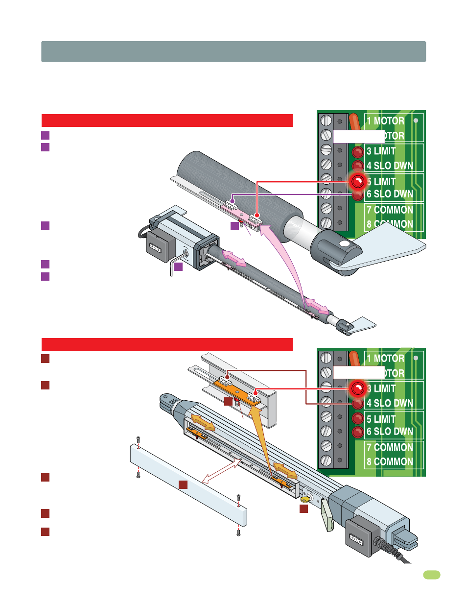
2.3 Limit Sensors Adjustment -
Select your specific operator
The limit sensors on the operator MUST be adjusted to control the travel of the gate and to precisely set the full open and full
closed position of the gate.
Use ONLY the limit sensor instructions for your specific operator type (6002, 6003, 6004 or
6400).
This feature is especially useful in applications where the gate opens partially, such as on a curved driveway.
6 Slow Down
4 Slow Down
5 Limit
3 Limit
limit nut
Manually move the gate to the desired
open or closed position. Loosen the limit
nut and slowly slide the limit assembly
until the corresponding
LIMIT LED
on the circuit board lights up
and
tighten nut.
Manually move the gate to
other position. Repeat process with the
other limit assembly.
Manually move the gate to the desired
open or closed position. Loosen
limit nut and slowly slide the limit
assembly until the corresponding
LIMIT LED on the circuit board lights
up
and tighten nut.
Manually move the
gate to other position.
Repeat process with the
other limit assembly.
Re-lock actuator arm with
allen wrench and test the
gate stopping positions.
Re-adjust if necessary.
Adjust the Secondary actuator limit
sensors if dual actuators have been
installed. SW 1, switch 2 controls secondary
actuator opening direction. SW 1, switch 7 MUST
be ON when using dual actuators (See page 18).
With actuator cover removed, manually un-lock actuator arm with allen wrench.
A
A
B
C
E
Re-install the actuator cover.
D
B
Limit Assembly
Limit Assembly
OPE
N
O P
E N
limit nut
Manually un-lock actuator arm with key
and remove limit cover with 4 screws.
A
A
B
C
D
E
B
OPEN
CL
OS
E
Power to the circuit board must be ON when adjusting the limit sensors.
Power to the circuit board must be ON when adjusting the limit sensors.
6002 Limit Sensors ONLY
6003 Limit Sensors ONLY
3 Limit
5 Limit
5 Limit
4 Slo Dwn
6 Slo Dwn
3 Limit
4 Slo Dwn
6 Slo Dwn
Limit LEDs
A
Limit LEDs
Limit Cover
Adjust the secondary actuator limit sensors if dual
actuators have been installed. SW 1, switch 2 controls
secondary actuator opening direction. SW 1, switch 7
MUST be ON when using dual actuators (See page 18).
Re-install the limit cover.
Re-lock actuator arm with
key and test the gate stopping
positions. Re-adjust if necessary.
Note: 3 and 5 limit LEDs can be Open
or Close limits depending on SW 1,
switch 1 and 2 settings (See page 17).
Note: 3 and 5 limit LEDs can be
Open or Close limits depending
on SW 1, switch 1 and 2
settings (See page 17).