2 dip-switches, 6002 only, 6004 only – Controlled Products Systems Group 4302-111 User Manual
Page 19: Sw 1 (top 8 switches) definitions on next page
4302-065-F-1-13
17
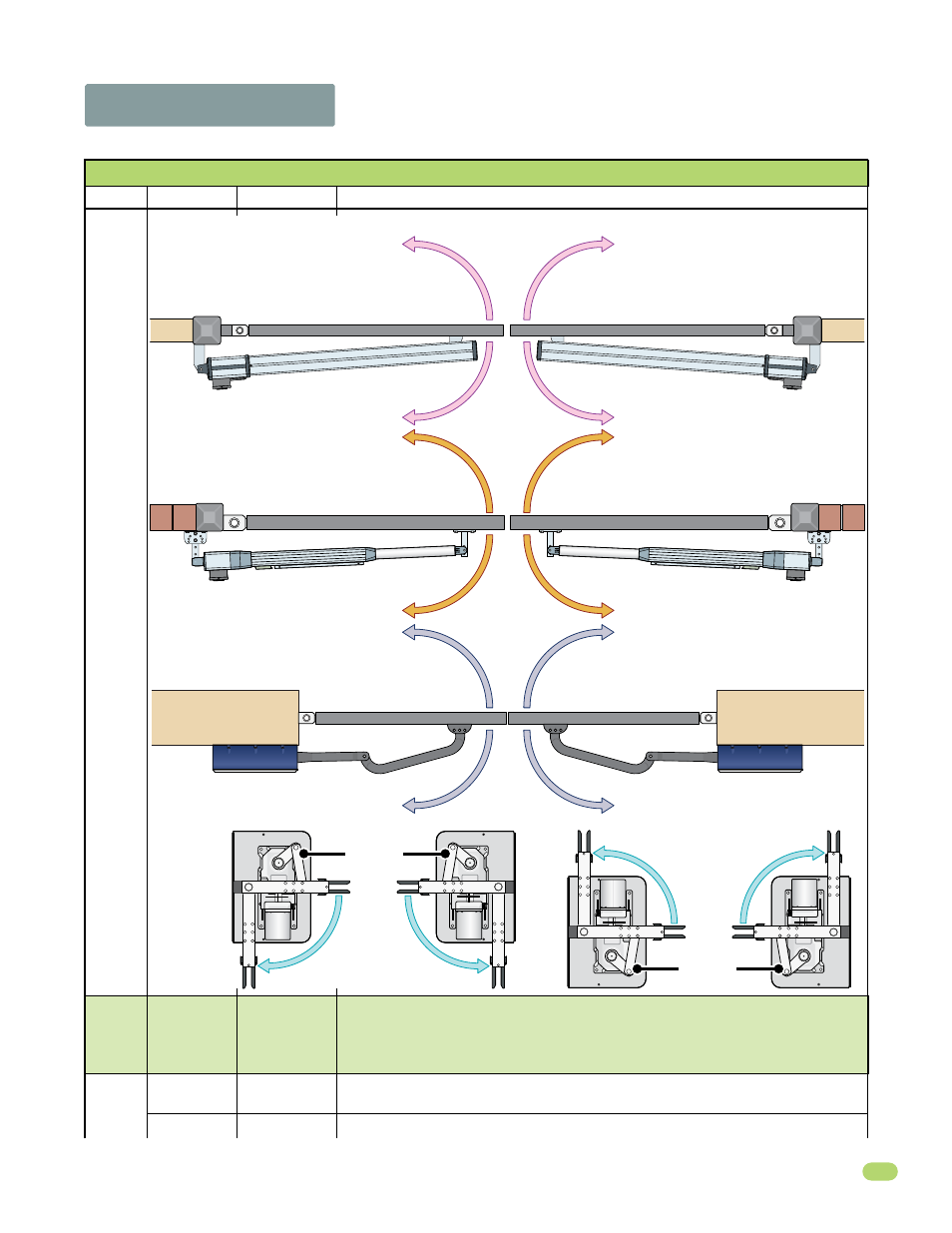
2.2 DIP-Switches
Switch
Function
Setting
Description
OFF
1
Opening
Direction of
SECONDARY
Operator
2
3
Terminal #4 is output from plug-in exit loop detector installed in EXIT loop port.
SW 1 (Top 8 Switches) Definitions on next page
Whenever any programming or switch setting on the control board is changed, press the reset button for new settings to take effect.
Same opening directions as illustrated above for the primary operator type.
• Switch 2 will be the SAME setting as switch 1 for the 6002 or 6003 ONLY.
• Switch 2 will be the OPPOSITE setting as switch 1 for the 6004 and 6400 ONLY.
Note: SW1, switch 7 MUST also be ON when using a secondary operator.
Exit Loop Port
Output
Open Input
ON (normal)
Terminal #4 is normal open command.
Opening Direction of PRIMARY Operator
ON setting.
Opens clockwise.
ON setting.
Opens counter-clockwise.
OFF setting.
Opens counter-clockwise.
OFF setting.
Opens clockwise.
6002 ONLY
ON setting.
Opens clockwise.
ON setting.
Opens counter-clockwise.
OFF setting.
Opens counter-clockwise.
OFF setting.
Opens clockwise.
6003 ONLY
6400
ONLY
OFF setting.
OFF setting.
ON setting.
ON setting.
Same Drive Motor
Orientation
Open
Open
Open
Open
Closed
Closed
OFF setting.
Opens clockwise.
ON setting.
Opens counter-clockwise.
ON setting.
Opens counter-clockwise.
OFF setting.
Opens clockwise.
Left-Side
Right-Side
6004 ONLY
SW 1 Switches continued on next page
Same Drive Motor
Orientation