2 dip-switches continued, Sw 1 switch definitions: sw 2 switch definitions, Sw 2 (bottom 4 switches) – Controlled Products Systems Group 4302-111 User Manual
Page 20
4302-065-F-1-13
18
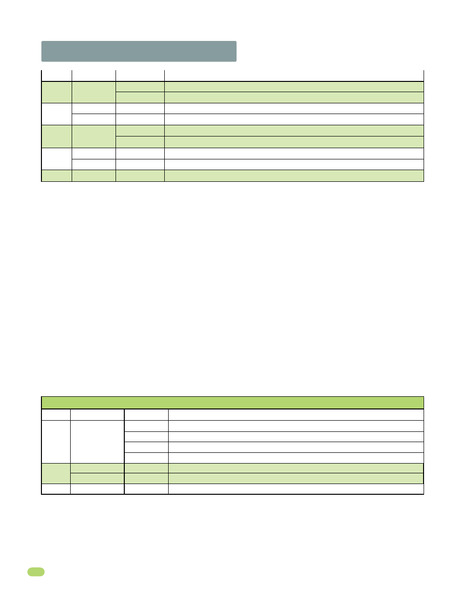
2.2 DIP-Switches Continued
Switch
Function
Setting
Description
SW 2 (Bottom 4 Switches)
SW 1 Switch Definitions:
SW 2 Switch Definitions:
SW 2-Switch 1 and 2:
These work in conjunction with each other and determine when the relay on the board will be activated. This
relay can be used as a switch for various functions such as illuminating a warning light when the gate is moving, or turning on a
green light when the gate is full open. This relay is not available for these uses if it is being used for the shadow loop function.
SW 2-Switch 3:
Used for a maglock (N.C.) when turned ON. Leave in the OFF position if a maglock is NOT used.
SW 2-Switch 4:
Spare switch. Leave in OFF position.
1-OFF
1-OFF
1-ON
1-ON
2-OFF
2-ON
2-OFF
2-ON
Relay activates when gate is fully open.
Relay activates when gate is not closed.
Relay activates when gate is opening and open. Shadow loop setting if used.
Relay activates when gate is opening and closing.
Spare
Leave in the OFF position.
OFF
Relay
Operation
1 and 2
3
4
1 second delay to disengage maglock.
Leave in the OFF position if a maglock is NOT used.
ON
OFF
Maglock Used
No Maglock
SW 1-Switch 1:
PRIMARY motor direction switch - Must OPEN the primary gate upon initial AC power up and open command. If
the open command begins to close the primary gate, turn AC power off and reverse this switch.
SW 1-Switch 2:
SECONDARY motor direction switch - Must OPEN the secondary gate upon initial AC power up and open
command. If the open command begins to close the secondary gate, turn AC power off and reverse this switch.
SW 1-Switch 3:
Determines if the output of the loop detector (DoorKing plug-in loop detectors only) installed into the EXIT loop
port will be sent directly to the microprocessor to open the gate (Normal), or if the output is directed to Terminal #4 where it can
then be connected to other input terminals.
SW 1-Switch 4:
Turns the auto-close timer on or off. Maximum time that the close timer can be set for is approximately 23 secs.
SW 1-Switch 5:
OFF setting is Standard Reverse for a CLOSING gate. An input to terminal #8 (e.g.: photo beam gets obstructed)
AND/OR reverse loops get activated will stop and reverse the gate back to the full open position. If the auto-close timer is ON,
when gate reaches the open position, timer will not close the gate. Another input command is needed to reset and close the
gate. DO Not use the ON setting.
SW 1-Switch 6:
When the gate overlap is OFF, the DUAL gate operators will start the open and close cycles at the same time.
This is the normal setting for a SINGLE gate operator.
Turning the gate overlap ON when using dual gate operators will cause the secondary operator to start the OPEN cycle 1-2
seconds before the primary operator. The primary operator will start the CLOSE cycle 1-2 seconds before the secondary
operator. This feature is useful when a magnetic lock is used to secure the gates.
SW 1-Switch 7:
Sets up the circuit board for single or dual (Primary / Secondary) gate operation.
SW 1-Switch 8:
Input power switch. Switch MUST be in the OFF position for the 115 VAC control box. DO NOT turn switch ON.
Switch
Function
Setting
Description
OFF (normal)
ON
OFF
ON
Reverse
Not Used
Overlapping
Gates
5
6
Terminal #8 is a standard Reverse input.
On setting is NOT used.
Both operators start at the same time.
Secondary operator opens 1-2 seconds before primary operator. Vice-versa when closing.
OFF
ON
Single
Dual
Switch must be OFF for single operator.
Switch must be ON when (dual) operators are used.
SW 1 (Top 8 Switches) continued
Input Power
Switch MUST be in the OFF position.
OFF
8
7
OFF
ON
Auto-Close
Timer
4
Auto-close timer is OFF. Manual input required to close gate.
Auto-close timer is ON. Adjustable from 1-23 seconds.