6 loop detector wiring, Automatic exit loop, Reverse loops – Controlled Products Systems Group 4302-111 User Manual
Page 16: Shadow loop, Ba c
4302-065-F-1-13
14
Reverse
Reverse
Shadow
Automatic Exit
Secure Side
Inside Propert
y
Non-Secure
Side
Outside
Propert
y
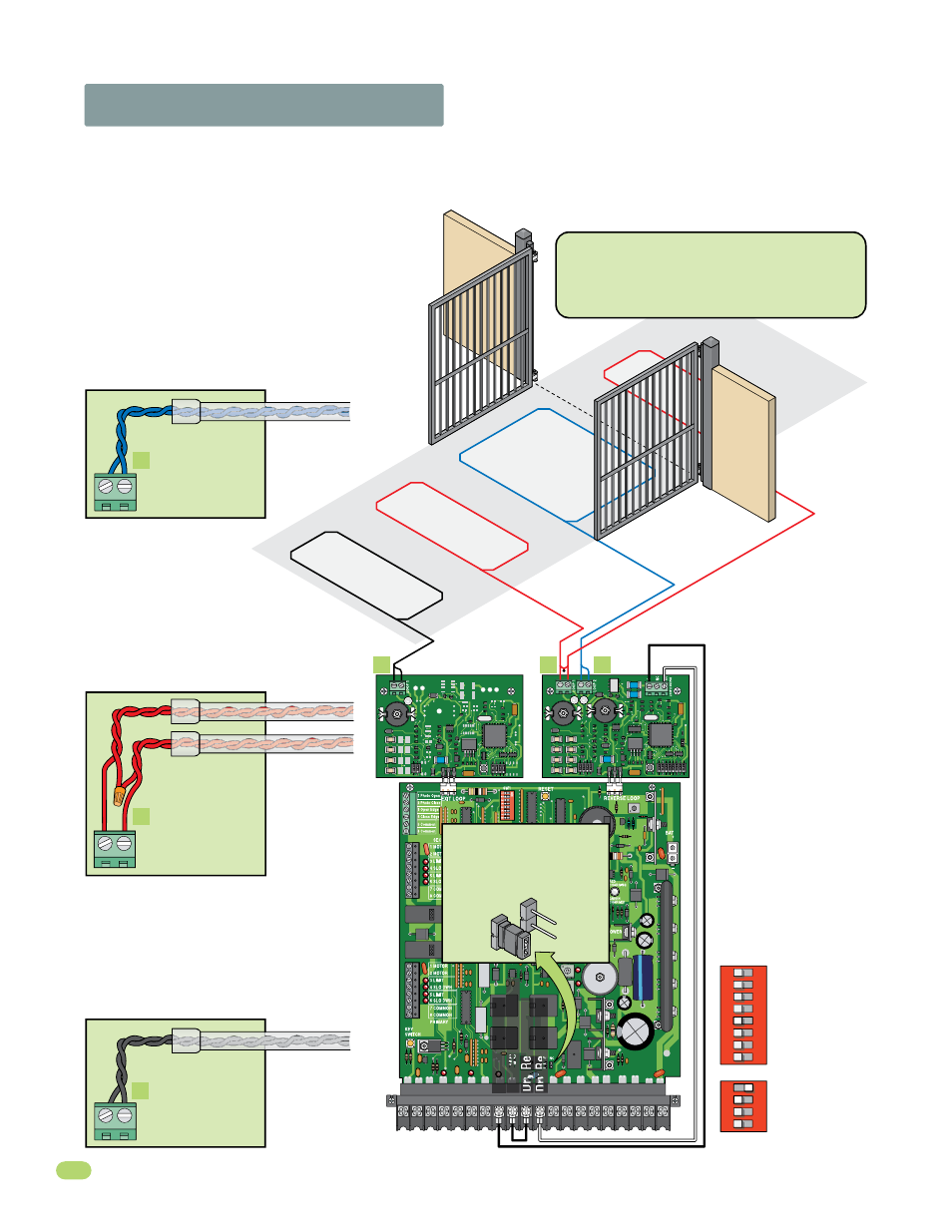
1.6 Loop Detector Wiring
Loop detector wiring is
shown for DoorKing
plug-in loop detectors
P/N 9409-010 and P/N
9410-010 only. If other
loop detectors are used,
refer to the installation
instructions supplied
with those detectors for
wiring and separate
power instructions.
Automatic Exit Loop
Automatically opens the gate for exiting
vehicles without having to use a transmitter
or keypad (Free exit).
Reverse Loops
Reverse loops prevent the gate
from closing on a vehicle in or
near the gate’s swing pathway.
Shadow Loop
The shadow loop is only active
when the gate is in the full open position. Vehicles in
the shadow area will activate it. It will not allow the
gate to close unless this area is clear. After a closing
cycle begins, the shadow loop will not reverse the
gate. Reverse loops work in conjunction with the
shadow loop and both type loops should be used.
1
2
3
4
5
6
7
8 9 10 11
12 13 14 15 16 17 18 19 20
9410
9409
Com
N.O.
To help protect the operator from accidentally closing on vehicles in the gate’s path, DoorKing highly recommends that loops
and loop detectors are used. A loop detection system will sense a vehicle like a metal detector and send a signal to the gate
operator preventing the gate from automatically opening or closing on a vehicle when it is in the gate’s path. DoorKing recom-
mends that a licensed installer perform this work.
Reverse loop
lead-in wires are
twisted approx.
6 twists per foot
and are wired in
series.
B
B
A
C
LOOP 1
PVC conduit to
Control box.
PVC conduit to
Control box.
Single Channel
Dual Channel
The circuit board relay is
used for the shadow loop
and must be set to N.O.
C
LOOP 1
Exit loop lead-in
wires are twisted
approx. 6 twists
per foot.
PVC conduit to
Control box.
A
LOOP 2
Shadow loop
lead-in wires are
twisted approx.
6 twists per foot.
4302
SW 1, switch 5
is OFF.
SW 2, switch 1
is ON and
switch 2 is OFF.
Shadow Loop
DIP-Switch Settings
SW 1
1
ON
2
3
4
5
6
7
8
SW 2
1
ON
2
3
4
Shadow Loop Output
DoorKing offers a free “Loop and Loop-
Detectors Information Manual” PDF located
at Doorking’s web site for more information.
www.dkaccess.com
NO
NC
Standard Reverse
Low V
oltage Common
Dr
y Relay Contact
Dr
y Relay Contact