7 high voltage wiring and battery connection, Danger, Control box must be properly grounded – Controlled Products Systems Group 4302-111 User Manual
Page 17: Caution, Chassis ground, Ac power switch battery plug, External power disconnect switch
4302-065-F-1-13
15
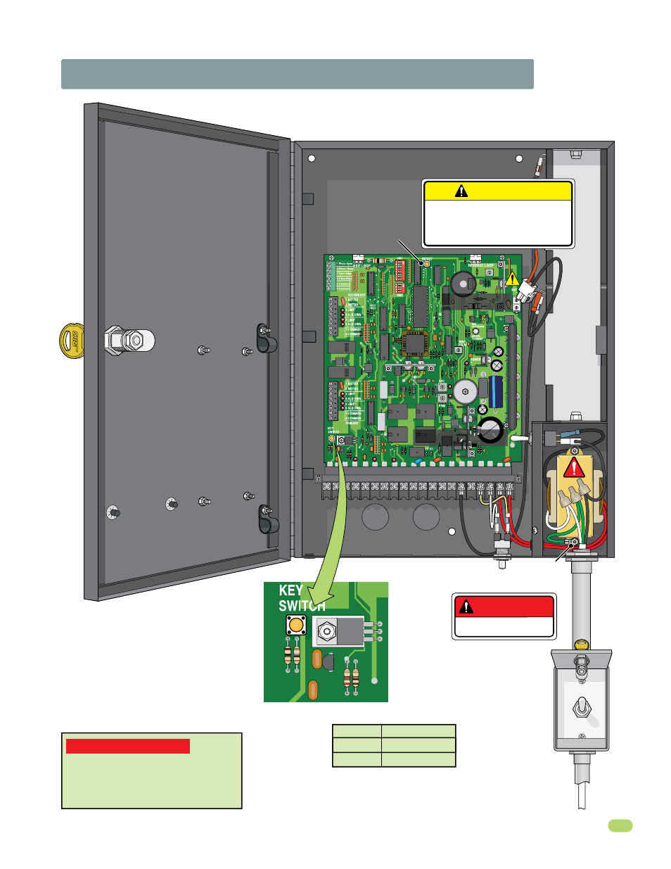
1.7 High Voltage Wiring and Battery Connection
Important Power Note:
To turn-off
ALL power to the operator, the AC
power switch must be turned off AND
the battery plug must be disconnected
from the circuit board.
1
2
3
4
5
6
7 8
9 10 11 12 13 14 15 16 17 18 19 20
RED 24V RED
BLK 115V WHT
Chassis
Ground
To Cycle Operator:
Alarm
Reset
Button
Input Power Wire Table
Conduit
Reset Button
DoorKing recommends that a surge
suppressor be installed on the high
voltage power lines.
P/N 1879-080
DANGER
HIGH VOLTAGE!
CAUTION
Do not connect the battery to
the circuit board until power
is needed to test the operator.
1
7
6
5
4
3
2
CONTROL BOX MUST BE PROPERLY GROUNDED!!
4302
12 V
o
lt 3 Amp/Hr Batter
y
12 V
o
lt 3 Amp/Hr Batter
y
AC Power Switch
Battery Plug
Wire Size
Distance
14 AWG
12 AWG
Up to 200 ft
Beyond 200 ft
After power has been connected, activate the
operator by pressing the key switch button.
DO NOT
cycle operator before DIP-switches
and limit sensors have been adjusted,
damage could occur to gate and operator
(See pages 17-21 to adjust DIP-switches and
limit sensors).
Input
Power
Wire
Note: A separate power
disconnect switch may be
needed in your area. Check
local building codes before
installation.
External
Power
Disconnect
Switch
AC POWER
ON
OFF
Connect 115 VAC input power wires:
Black to transformer’s black (Hot).
White to transformer’s white (Neutral).
Green to chassis ground.