Auto-close timer, Dip-switches dry relay contact, Inherent reverse sensors – Controlled Products Systems Group 4302-111 User Manual
Page 18: Plug-in loop detector plug-in loop detector, Self test, Alarm reset button, How leds function
4302-065-F-1-13
16
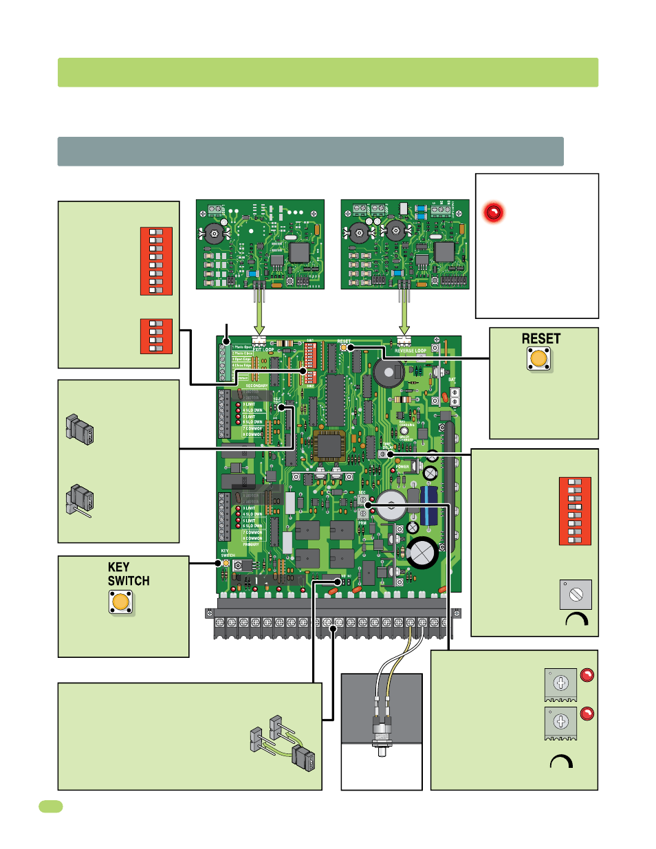
2.1 4302 Circuit Board Description and Adjustments
SECTION 2 - ADJUSTMENTS
The switch settings and adjustments in this section should be made after your installation and wiring to the operator(s) is
complete. Whenever any programming or switch setting on the control board are changed, press the reset switch for new
settings to take effect.
•
Auto-close
timer (when
turned ON) SW 1,
switch 4.
Adjust from 1
second (full
counter clockwise)
to approximately
23 seconds (full
clockwise).
Dry relay contacts (terminals 10-11) can
be set for Normally Open (NO) or
Normally Closed (NC) operation by
placing the relay shorting bar on the N.O.
or N.C. pins respectively.
(Shadow loop function if used, N.O., see page 14).
Press reset button to
activate changed control
board settings.
Turns OFF activated
alarm.
Cycles the operator when
pressed. Will use Auto-Close
timer when turned ON.
NO
NC
TIME
DELAY
1
23
Auto-Close Timer
Reverse Loop Port
Exit Loop Port
Batter
y
Plug
See page 15.
UL 325 Terminal
See page 11.
Set DIP-switches
on the circuit
board to the
desired setting.
See switch-setting
charts on next 2
pages.
DIP-Switches
Dry Relay Contact
Adjust reversing
sensitivity for:
PRIMARY (single) and
SECONDARY (dual)
operators. See page 22.
SEC
PRM
Min
Max
Sensitivity
Inherent
Reverse Sensors
1
2
3
4
5
6
7
8
9
10 11
12 13 14 15 16 17 18 19 20
Plug-In Loop Detector Plug-In Loop Detector
9410 Single Channel
9409 Dual Channel
4302
SW 1
1
ON
2
3
4
5
6
7
8
SW 1
1
ON
2
3
4
5
6
7
8
SW 2
1
ON
2
3
4
Self test mode is
for bench checks
ONLY. The
operator will
continually cycle
the gate.
The jumper must
be set at normal
mode to function.
Self Test
Mode
Normal
Mode
Self Test
SECONDARY
Operator
See page 10.
PRIMARY
Operator
See page 10.
Limit LEDs
Input LEDs
Main Terminal
See pages 12-13.
Limit LEDs
See pages 19-20.
See page 14.
How LEDs Function
Illuminated LEDs
Indicates that low voltage
power is being applied to
the circuit board.
Input LEDs should be OFF and
will only illuminate when the
input wired to the corresponding
main terminal is activated.
Limit LEDs will only illuminate
when the respective limit sensor
has been activated.
Alarm Reset
Button
See
page
24.
Turns
alarm
OFF.