Chapin 62000 User Manual
Page 5
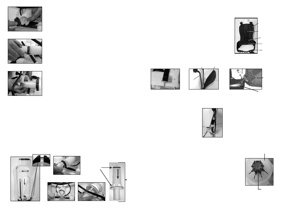
Base Tube
Lumbar
Support
INSTALLING THE SHOULDER STRAP
The backpack strap is provided with multiple features including
shoulder strap, chest strap, waist belt, lumbar support and back pad
(figure 1). The top of both the shoulder straps and back pad straps
are attached to the top of the tank and are removable. The back pad
strap attaches to the bottom of the tank (figure 2). The back pad is
attached to its strap with velcro and is removable ( figure3). The
strap from the lumbar support attaches to the base tube on the
bottom of the tank (figure 4).
Figure 2
Back Pad strap attachment
Figure 3
Removable Back Pad
Figure 4
Strap Attachment
Back Pad
Strap
Velcro
Attachment
Removable
Back Pad
Figure 1
Strap Assembly
Shoulder
Strap
Back
Pad
Chest Strap
Lumbar
Support
Waist
Belt
WAND CLIP
The wand can be attached to the pump
handle using the wand clip.
SPRAYER COMPONENTS & USE INFORMATION, Continued
9F
7) Appliquez un peu de pétrolatum à l'intérieur de la paroi du
cylindre du piston et sur le collier, et réinstallez l'assemblage du
piston dans le cylindre du piston.
8) Insérez le piston incliné par rapport au bord d'entrée du
collier placé sur la fente du cylindre du piston. Boulonnez
l'assemblage du piston à l'arbre de la pompe en utilisant les
boulons du levier.
9) Replacez le bouchon protecteur. Resserrez l'écrou et le
boulon. Réinstallez la poignée de la pompe. Replacez le
boyau et fixez fermement la pince du boyau en place.
Figure 9
Figure 8
Figure 7
DÉMONTER ET RÉPARER L'ASSEMBLAGE DE LA POMPE
B
Figure 2b
Figure 3a
Figure 3b
Figure 1
Joint torique
de la
chambre de
pression
Figure 2a
Pince
Assem-
blage de
pompe
Ne retirez le cylindre de compression que si le filtre à cartouche est bloqué ou si le pulvérisateur
fuit à l'endroit où le cylindre de pression et la cuve se joignent.
DÉMONTER ET RÉPARER L'ASSEMBLAGE DE LA POMPE
1. Dégagez la pression du pulvérisateur et retirez tout le liquide de la chambre de pression et de la cuve.
2. Retirez le boyau.
3. Retirez le filtre dans le réservoir du cylindre de pression (qui se trouve à l'intérieur du réservoir - fig.1).
4. Retirez les 2 boulons rattachant le levier du pivot à l'arbre de la pompe et retirez l'assemblage du piston
(fig. 2a et 2b).
5. Retirez la large pince retenant la chambre de pression et la cuve ensemble (fig. 1).
6. Faites basculer la chambre de pression d'avant à arrière et enfoncez pour le libérer de la cuve (fig. 1).
7. Après l'avoir libéré, tout l'assemblage de la pompe peut Ítre retiré en le faisant passer à travers
l'armature de base (fig. 3a et 3b).
PRESSURE REGULATOR
The spray tank and the pressure chamber are separate compartments in
the sprayer. Pressure is maintained in a separate pressure chamber
within the unit and is built to withstand normal operating pressure. The
backpack sprayer has a built-in, adjustable regulator to control spray
pressure. If required adjust the regulator before filling the sprayer tank. To
adjust, first remove the tank cap and filter basket. Look into the tank to
view the top of the regulator. There are four “fingers” on the regulator’s
knob. The fingers are numbered 1, 2, 3, and 4. Finger 1=30 psi, Finger
2=45 psi, Finger 3=60 psi, and Finger 4=80 psi. The higher you set the
pressure, the more liquid will exit the sprayer in a given amount of time.
Note: the higher the pressure is set, the smaller the droplets. Therefore,
there will be more “drift” in the expelled liquid at higher pressures. To
adjust, push down the regulator knob and rotate to align with the
alignment pin to the desired number.
30psi
45psi
60psi
80psi
Pressure
Chamber
Pressure
Regulator
4E