Chapin 7215023 User Manual
Warning, Parts, piezas, pièces, Pressurizing and spraying
Hazard: Improper use or failure to follow instructions can result in explosive failure
causing serious eye or other injury.
For safe use of this product you must read and follow
all instructions. Do not leave a pressurized sprayer in the hot sun. Heat can cause pressure
build-up. Do not store or le
ave solution in tank after use. Always wear goggles, gloves, long
sleeve shirt, long pants and full foot protection when spraying. Never use any tool to remove
pump if there is pressure in sprayer. Never stand with face or body over
top of tank when
pumping or loosening pump to prevent ejecting pump assembly and/or solution from strik-
ing and injuring you. Never pressurize sprayer by any means other than the original pump.
Do not attempt to modify or repair this product except with original manufacturer’s parts.
Never spray flammable materials or heat, pressure, or gas producing chemicals. Always
read and follow manufacturer’s instructions before use with this sprayer as some chemi-
cals may be hazardous when used with this sprayer.
WARNING!
Sk-1113-1
Printed in USA
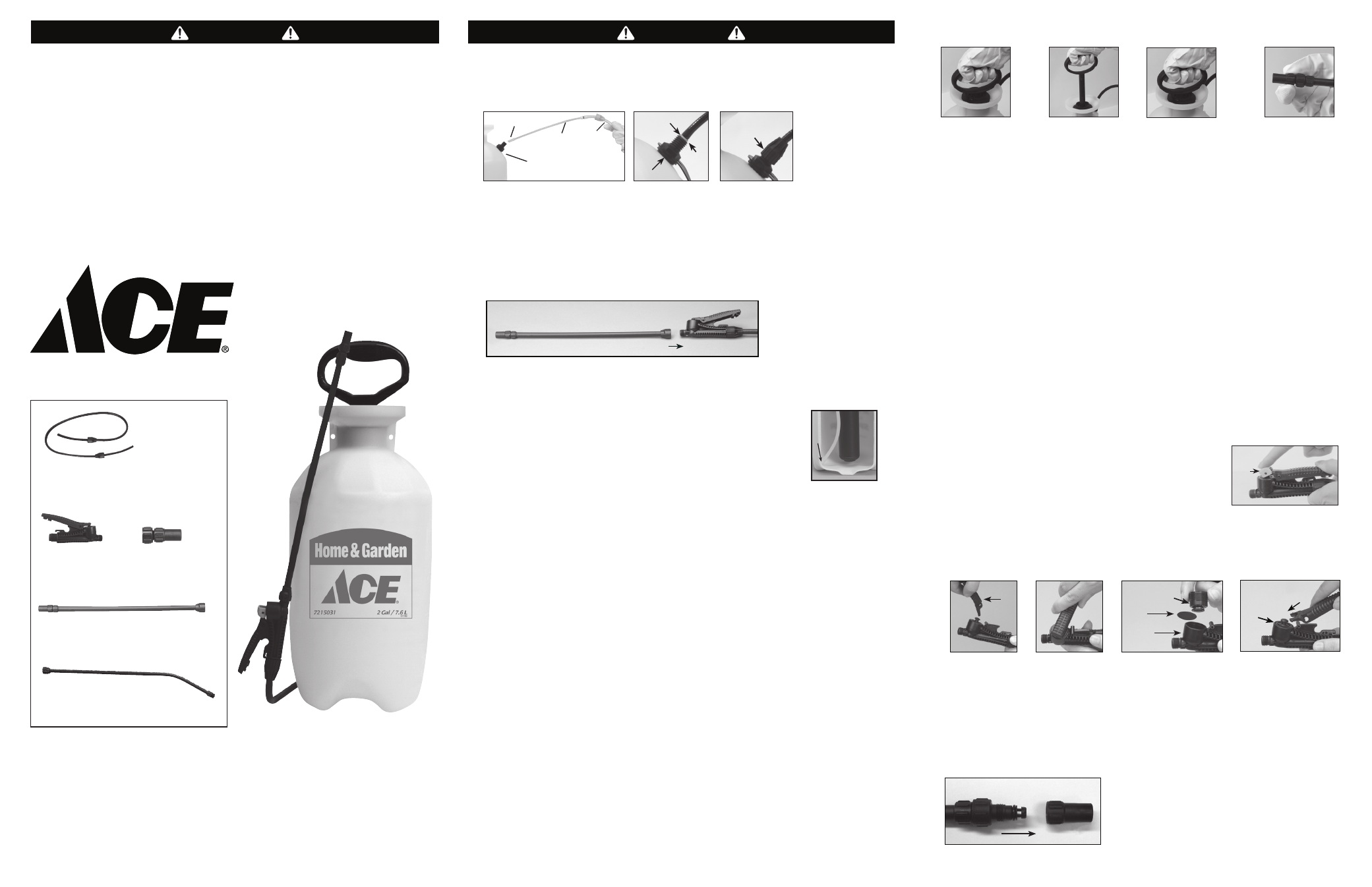
1. Hose to Tank
2. Nozzle / Extension Wand
Attach wand to shut-off handle.
3. Filter
The filter helps prevent clogging while spraying. It is located on the
end of the outlet tube inside your sprayer tank.To clean filter, remove
the discharge assembly from the tank (Fig.1A). Make sure the filter is
positioned at the bottom of the tank as pictured (Fig. 3A).
1) Do: Check tightness of hose nut to be sure hose is securely attached to the tank outlet.
2) Do: Inspect hose for deterioration, cracks, softness, or brittleness. If any of these conditions
are found, replace hose before using. Replace with original manufacturer’s parts only.
3) Do: Remove pump (see Filling, Pressurizing and Spraying Instructions), inspect interior
and exterior of tank for signs of deterioration of body and bottom. Any sign of
deterioration indicates possible tank weakening and could result in explosive bursting
under pressure. If any of these signs are found, discard tank immediately and replace. Do
not attempt to patch leaks, etc., as this could result in serious injury.
4) Do: Follow Filling, Pressurizing and Spraying Instructions, except use water only (Pump
plunger 10-20 strokes and inspect for leaks).
5) Do: Direct shut-off away from you and open to make sure discharge is not clogged.
6) Do: If unit passes this test, release pressure (see Pressure Releasing Instructions), empty
tank, and proceed with Filling, Pressurizing and Spraying Instructions.
4. Pre-Use Check
5. Filling
1) Do: Turn pump handle counterclockwise and remove pump
2) Do: Prepare spray solution following all directions and safety warnings on chemical label.
3) Do: Fill tank to no more than the proper gallon marker. Do NOT: overfill to
accommodate pump.
4) Do: Check pump to make sure that no grass or dirt is stuck to barrel. Replace pump in
tank and tighten securely.
7. To Release Pressure
Do:
With pump facing away, turn locked handle counterclockwise until air begins to escape.
Stop turning handle when you hear air escaping. Do: Point pump away until all air has
escaped.
8. Care, Storage and Maintenance
1) Do: Rinse tank thoroughly with water only, empty, refill with water. Follow Filling,
Pressurizing and Spraying Instructions, except pump unit only 8-10 strokes.
2) Do: Open shut-off and allow water to run through discharge assembly.
3) Do: Release pressure (Follow Pressure Release Instructions), remove pump and empty
sprayer.
4) Do: Store sprayer tank upside down, with pump removed, in a warm dry location.
5) Do: Periodically oil pump by dropping 10-12 drops of light oil down pump rod through
opening in cover.
011190 (A) R0210
Note: Your particular sprayer may not include all parts pictured above.
Nota: Es posible que este pulverizador en particular no incluya todas las partes que se ilustran arriba.
Remarque : Votre pulvérisateur particulier pourrait ne pas inclure toutes les pièces illustrées plus haut.
Discharge/ Tool Holder Assembly
• Insert the outlet tube portion of the discharge assembly into the tank adapter (Fig. 1A).
• Firmly insert the outlet tube portion into the tank adapter (Fig. 1B) leaving no gap
between the tank adapter and outlet tube adapter. Firmly tighten the retaining nut to the
tank adapter (Fig. 1C).
WARNING!
To prevent hose from blowing off, hose must cover both barbs on the outlet tube adapter and
touch flange (Fig. 1B) before hose nut is securely tightened (Fig. 1C).
1A
1C
Retaining Nut -
Securely tightened.
Tool
Holder
Outlet
Tube
Discharge
Assembly
Filter
3A
Parts, Piezas, Pièces
6-2001
Hose Kit: 2 nuts, 2 barbs and hose
Juego de manguera: 2 tuercas ,2 lengüetas y manguera.
Nécessaire de tuyau: Deux écrous, deux ardillons et tuyau
6-2000
Shut-off Handle
Mango de cierre
Poignée du robinet
6-6003
Nozzle
Boquilla
Buse
6. Pressurizing and Spraying
Do:
Turn handle
clockwise to tighten.
Push handle down,
turn 1/4 turn counter-
clockwise to release.
Do:
Pump
until you feel
resistance.
Do:
Push handle, down,
turn 1/4 turn clockwise
to lock. Begin spray-
ing. Re-pump sprayer
as required to maintain
spray force.
Do:
Turn end of
nozzle to adjust spray
pattern.
6A
6C
6B
6D
1B
No Gap
Tank
Adapter
Outlet
Tube
Adapter
Filter
Pull handle
straight up.
Insert notches
from underside of
handle into plunger
grooves and turn
counterclockwise.
Remove plunger and
diaphragm. Clean plunger,
diaphragm and body. Flip
diaphragm and replace.
Tighten plunger clockwise
until flush to top of shut-off
body. Do not over-tighten
or unit may not spray. Slide
forks under plunger, push
handle down until it snaps
into place.
10. Troubleshooting
-
Tank pressurizes but does not spray.
10A
10B
10C
Handle
Plunger
Body
Diaphragm
10D
Plunger flush
with body
WARNING:
Release pressure in tank before troubleshooting.
Clean Nozzle Assembly (Fig. 10E) -Remove nozzle cap. Clean and re-assemble.
Clean shut-off (Fig. 10A- 10D)
9. Fatigue-Free Spraying
For constant spraying, push down on shut-off handle and
move grey locking mechanism away from you. To release,
squeeze handle and move the grey locking mechanism back
towards you. ( Not all models are provided with this feature).
2a
10E
Nozzle Cap
6-7749
Extension wand (poly)
Vara de extensión
Rallonge
Repair Parts Kit Gaskets and Seals (not included),
Juego de piezas de reparación, empaquetaduras y juntas (no incluido)
Kit de pièces de réparation, joints et garniture d’étanchéité (non inclus) 6-1925
9A
Locking
mechanism
301277-1
Extension wand (poly)
Vara de extensión
Rallonge