Chapin 62000 User Manual
Page 3
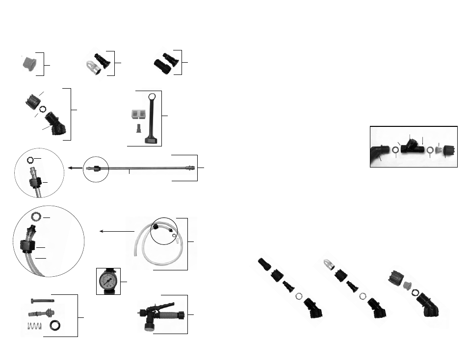
INFORMATION DE COMMANDE DE PIÈCES DE RECHANGE
11F
ASSEMBLAGE DE BUSE
Bouchon
vissé
Joint
torique
Tube
6-8149
Assemblage
de tube
6-8096
Buse en
éventail
plat
6-8093
Buse poly
ajustable
6-8122
Buse de
laiton
ajustable
6-8148
Trousse
de buse
Écrou de
blocage
Buse joint
d’étanchéite
Coude avec
joint torique
6-8175
Assemblage
d’arrêt
6-8120B
Trousse de
réparation de
robinet d’arrêt
6-8177
Jauge
6-8105
Assemblage
du boyau
Rondelle
de boyau
Écrou de blocage
Boyau
6-8169
Trousse de
remplacement
APPLICATIONS & USE FOR YOUR SPRAYER
Avoid using a sprayer for general cleaning purposes if plant protection or herbicide chemicals have already
been used in the sprayer. If a sprayer has been used for plant protection or as an herbicide, clean the
sprayer completely (see page 5) before using.
Plant Food: Use different spray patterns for optimum foliage feeding or for fungicide and pesticide
application.
Herbicides: Reduce weeds and unwanted plants but avoid using the same sprayer for plant feeding or
protection without thoroughly cleaning (see page 5) the sprayer first.
General Household Use: Apply detergents, vinegar, cleaning solutions, warm water (do not exceed
120°F/49°C) or nontoxic household cleaning chemicals for carpets, floors, walls, glass, counter tops and
ceilings. DO NOT use sprayer that has been used with herbicides, pesticides or other toxic chemicals for
household applications.
General Outdoor Use: Use the sprayer for cleaning windows or with a detergent for general purpose
cleaning. Other applications include wood preservatives, waxes, water proofing, and diluted household
bleach (max. 1 part household bleach to 9 parts water solution).
2E
NOZZLE ASSEMBLY
Figure 1-2
Unscrew the nozzle cap (1) from the nozzle body (3) with retaining nut (2) fastened tightly to the elbow
(5). Unscrew the retaining nut (2). Push the nozzle body (3) with the nozzle gasket (4) out of the
retaining nut (2). To reinstall the nozzle, reverse the above instructions.
Figure 3
Unscrew the retaining nut from the elbow and push the fan nozzle tip and gasket out of the retaining nut. To
reinstall the nozzle, reverse the above instructions.
3. Nozzle
Body
2. Retaining
Nut
5. Elbow
4. Nozzle
Gasket
Figure 1
Figure 2
Figure 3
1. Poly
Nozzle Cap
1. Brass
Nozzle Cap
Elbow
Nozzle
Gasket
Fan Nozzle Tip
Retaining Nut
2. Retaining
Nut
3. Nozzle
Body
4. Nozzle
Gasket
5. Elbow
CF VALVE™ ASSEMBLY
Assemble nozzle gasket to inlet side of CF Valve™ and screw onto the
end of the elbow. Place the fan nozzle tip into the retaining nut and
then place the nozzle gasket on the fan nozzle tip flange. Screw this
assembly onto the outlet side of the CF Valve™. To uninstall the CF
Valve™, reverse the above instructions.
The CF Valve™ is intended to be used with a fixed nozzle. The Fan
nozzle tip provided is rated @ .4 GPM @ 40psi.
Elbow
Nozzle
Gasket
Inlet
(3/8 Thread)
CF Valve™
(1.5 BAR-21 psi)
Outlet
(3/8 thread)
Nozzle
Gasket
Fan
Nozzle Tip
Retaining
Nut
SPRAYER COMPONENTS & USE INFORMATION