Chapin 62000 User Manual
Page 11
3F
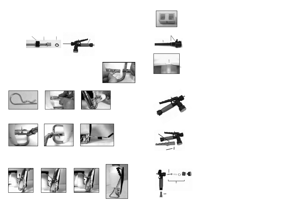
INFORMATION D'UTILISATION ET COMPOSANTS DU PULVÉRISATEUR, suite
Figure 1
Goupille fendue
Figure 2
Alignez les trous
Figure 3
Glissez la goupille à travers les trous.
Figure 5
Droitier
Figure 4
Gaucher
POIGNÉE DE POMPE ESCAMOTABLE
INSTALLER LA POIGNÉE DE POMPE
La poignée de pompe s'installe à l'une ou l'autre extrémité de l'arbre de la
pompe (A). Pour installer la poignée de pompe, placez la poignée (C) sur
l'arbre (A) en alignant le trou de la poignée de pompe et le trou de l'arbre.
Poussez le côté droit de la goupille fendue (B) à travers le trou aligné tel
qu'indiqué dans les figures 1 à 3. Il y a dans trous dans la poignée de la
pompe pour permettre un montage de gaucher (fig. 4) ou droitier (fig. 5).
ASSEMBLAGE DES TUBES
1. Assurez-vous que le joint torique est installé à l’extrémité du tube.
Insérez le tube dans le robinet d’arrêt.
2. Tournez et resserrez le capuchon vissé dans le sens horaire sur le robinet d’arrêt.
Tube
Robinet
d'arrêt
Joint torique
Capuchon
vissé
10E
Figure 6
Figure 5
Pressure
Regulator
8. At this point the filter cartridge in the pressure cylinder base can
be remove with pliers and cleaned or replaced (fig 4).
9. The pressure cylinder o-ring can also be replaced. DO NOT stretch
the o-ring over the bottom flange. Assemble the o-ring over the top
of the cylinder. Apply petroleum jelly to the o-ring before reinstalling
pressure cylinder asembly into the tank (fig. 3b).
10. The pressure regulator can also be replaced at this point if
necessary by unscrewing it from the pressure cylinder. If replacing
apply petroleum jelly to the pressure regulator o-rings before
installing (fig. 5).
11. Reassemble backwards from step 6 thru 2, performing each step
in reverse. Note: there is a notch/tab combination in the pressure
cylinder/tank to be used for alignment (fig. 6).
Figure 4
O-rings
Pressure
Cylinder Notch
Tank tab
C
B
1) Assembled shut-off valve (Figure 1).
2) Remove the retaining pin (A) (Figure 2) place the notched
end of the retaining pin on a hard surface and push down.
Remove the retaining pin and slide the handle off the valve.
Figure 1
Figure 2
Figure 3
A
Locking
Clip
DISASSEMBLING AND REPAIRING THE SHUT OFF VALVE
3) Remove the retaining nut (o-ring attached), spring, and valve
stem (B) (Figure 3). Replace worn parts. Lubricate the O-rings and
reassemble by reversing the steps above. Place the handle groove
in the slotted area of the valve stem and make sure the locking clip
is positioned in the neutral position (see “Helpful Spraying
Information” section). Insert the retaining pin. Push down on the
handle a few times to distribute the lubricant evenly. Check filter
(C) in end of shut-off valve for debris. Remove filter and flush
with water to clean out.
Valve
Stem
C
B
A
Relevez
Tournez
de 180º
Placez
dans la
fente
Pump Handle
Positioned For Use
(right hand shown)