ELRO HA68S Multi-zone professional alarm system USERS MANUAL User Manual
Page 9
-7-
-58-
A
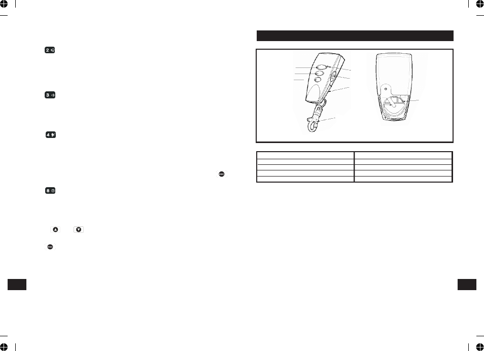
LED indicator
F
Key Chain Ring
B
Arm
G
Battery Cover
C
Partial Arm
H
Negative Polarity
D Disarm
I
Positive Polarity
E
Panic Switch
The Remote Control Unit is used to Arm, Partial Arm and Disarm the system.
The Remote Control also incorporates a Panic switch. Activating the Panic switch
will immediately initiate a Full Alarm condition whether the system is Armed or
Disarmed, (unless the system is in Service, Test or Program mode).
The Remote Control adopts a CR2032 type Lithium cell which under normal
conditions will have typical life in excess of 1 year. Under normal battery
conditions the LED on the Remote control will only illuminate when a button is
pressed. However, under low battery conditions this LED will flash every time
the button is pressed. When this occurs the batteries should be replaced as
soon as possible.
SETTING THE REMOTE CONTROL
1.Remove the rear cover by undoing the small screw on the rear of the Remote
Control.
2.Insert the battery ensuring that the +v terminal faces upwards away from
the PCB.
REMOTE CONTROL UNIT
Front
Back
B
C
D
A
E
G
F
H
I
CHIME
The Chime facility can only be operated with the system in Disarm mode.
Press to toggle the Chime facility between ON and OFF.
Note: If the Chime is ON and the system is then armed the Chime will remain
ON after the system is disarmed.
MUTE
The Mute facility can only be operated with the system in Disarm mode.
Press to toggle the Mute facility between ON and OFF.
Note: If the Mute is ON, no voice guidance will be made during operation. If the
mute is OFF, voice guidance will be active. However, if ‘LINE STATUS’ LED
illuminates while the mute is OFF, there is no voice guidance will be available.
LATCH KEY
Press to access the latch key function for quick programming.
EVENT-LOG
The Event Log will store the last 50 system Arm, disarm, alarm and detector
Low Battery events. The Event Log will record the time, date and details for
each event. If when the system is disarmed the “ALARM MEM’ LED is flashing
and the panel beeps every 10s, this indicates that an alarm has occurred. To
cancel the LED and stop the beeping you must access the event log or press
to eliminate the flashing ‘ALARM MEM’ LED and the beeping as well.
To access the Event Log, (with the system in Disarm):
Press .
The Event-Log will automatically start scrolling through and displaying the event
data starting with the most recent event. The data for each event is shown on
two screens, each screen will be displayed for 5 seconds before moving on to
the next screen and then the next event.
Use the and buttons to manually scroll through the event log to the
required position as necessary.
Press to return to Disarm.
TELEPHONE LINE DETECTION
When setting to the voice dialer and If ‘LINE STATUS’ LED is flashing, it implies
bad telephone line connection or telephone network being out of order. Check
the telephone line and re-test it.
When setting to the digital dialer and if ‘LINE STATUS’ LED is flashing, it implies
two causes of failure. One is bad telephone line connection or telephone
network being out of order. The other cause of failure is derived from the
central monitoring station. Consult with the central monitoring station for help.
EN
EN