ELRO HA68S Multi-zone professional alarm system USERS MANUAL User Manual
Page 10
-57-
-8-
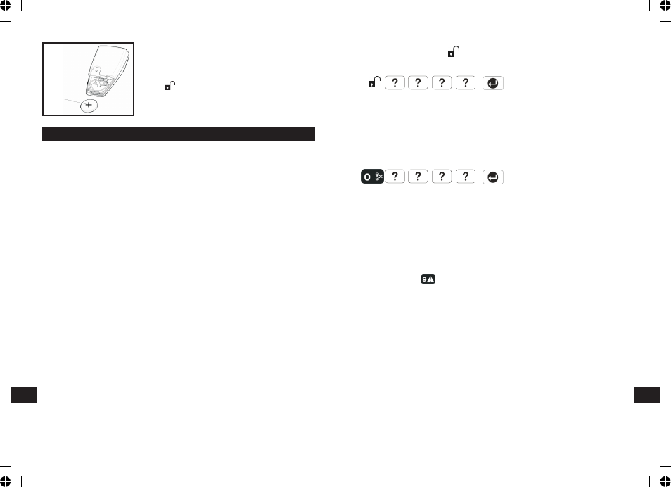
CONTROL PANEL
3. Replace the rear cover and fixing screw.
4. In order to communicate with the Control
Panel, the ID code of the Remote Control needs
to be learned by the Control Panel. By pressing
the button on the Remote Control will emit
the ID code to the Control Panel instantly,
subject to the Control Panel being set at the
User Setup mode.
LOCATING THE CONTROL PANEL
When choosing a suitable location for the Control Panel, the following points
should be considered.
1. The Control Panel should be located in a position out of sight of potential
intruders and in a safe location, but easily accessible for system operation.
2. The Control Panel should be mounted on a sound flat surface to ensure that
the rear tamper switch on the Control Panel is closed when the Panel is
mounted. The Control Panel should be mounted at a convenient height of
between 1.5 and 2m and in a position where it will be seen each day.
Note: If small children are in the household, a further consideration should
be given to keeping the units out of their reach.
3. It is recommended that the Control Panel should be positioned such that the
Exit/Entry tone (emitted by the Control Panel) can be heard from outside the
property.
4. The Control Panel should be mounted within a protected area so that any
intruder cannot reach the Control Panel without opening a protected door or
passing through an area protected by a PIR detector when the system is
armed.
5. The Control Panel must be located within reach of a mains socket.
6. If the telephone based functionality is to be used then the Control Panel will
need connecting to a convenient telephone point.
Note: It is recommended that the telephone connection lead is not extended
beyond 5m before connecting to a telephone master or secondary outlet.
7. Do not locate the Control Unit closer than 1m to any large metallic object,
(e.g. mirrors, radiators, etc) as this may affect the radio range of the Control
Panel.
Batterij
Remote Control:
Press the ‘DISARM’ button, .
Control Panel:
User Password
If the system is disarmed and the ‘ALARM MEM’ LED is flashing with the panel
beeping every few seconds, this indicates that an alarm condition has occurred.
Use the Event Log to find out and make a note of where the alarm occurred to
assist in tracing the cause of the alarm.
QUICK SET
To operate the quick set function and fully arm the system in 5s, overriding the
programmed exit delay. Press:
User Password
PANIC ALARM
A full Alarm condition can be immediately initiated
at any time (whether the system is Armed or Disarmed) in the event of threat
or danger by activating a Panic switch on either the Remote Control or the
Control Panel.
Remote Control:
Slide the Panic switch upwards.
Control Panel:
Press and hold the button for approximately 3 seconds.
The alarm will continue either for the alarm duration when the system will
automatically reset or until the system is disarmed.
TAMPER
If the battery cover of any device is removed or if the Siren or Control Panel are
removed from the wall then a Full Alarm condition will be initiated even if the
system is Disarmed. The alarm condition will continue either for the alarm
duration when the system will automatically reset or until the system is
Disarmed. The ‘ALARM MEM’ LED on the Control Panel will flash and the panel
will beep every few seconds to indicate an alarm has occurred.
Note: The Tamper protection facility on the Siren operates independently. If the
Tamper on the Siren is activated this will not be indicated at the Control Panel.
EN
EN