ELRO HA68S Multi-zone professional alarm system USERS MANUAL User Manual
Page 19
-17-
-48-
For double security, there are two tamper switches fitted on the Detector.
(FIGURE 2) Either removing the Detector from the protected door/window or
removing the battery cover will generate a full alarm condition.
The Magnetic Contact Detector is of self-contained wired Magnetic Contact. This
contact must be of a normally closed contact type with the contacts being
opened in order to generate an alarm condition.
CHOOSING A MOUNTING LOCATION
The Magnetic Contact Detector is suitable for mounting in dry interior locations
only.
Decide which doors/windows are to be protected by Magnetic Contact Detectors,
(usually the front and back doors as a minimum will have Magnetic Contact
Detectors fitted). Additional detectors may also be fitted where required to other
vulnerable doors or windows, (e.g. garage, patio/conservatory doors etc).
Note: Take care when fixing the Detector to a metal frame, or mounting within
1m of metalwork (i.e. radiators, water pipes, etc) as this could affect the radio
range of the device. If required, it may be necessary to space the magnet and
detector away from the metal surface using a plastic or wooden spacer to
achieve the necessary radio range.
INSTALLING THE MAGNETIC CONTACT DETECTORS
Ensure that the system is in Test Mode.
1. Undo and remove the fixing screw from
the bottom edge of the Detector.
Remove the battery cover by sliding
and lifting it off. (DO NOT use a screw
driver to lever the cover off).
2. Fit the 3.6V Lithium battery supplied,
with the negative (-) towards the
battery spring.
3. Mount the Detector to the fixed part of the frame along the opening edge
opposite the hinges using either the double sided adhesive tape or screws
provided.
If fixing the Detector with screws; fit the Keyhole slot in the top of the
Detector over the head of the smaller pan-head screw. Secure the bottom of
the Detector using the 12mm countersunk head screw fitted within the
battery compartment. You will need to drill out the centre of the fixing screw
hole using a 3mm drill. Do not over tighten the fixing screws as this may
distort or damage the casing.
4. Fit the Magnet to the moving part of the door/window opposite the Detector
using the adhesive tape or 15mm fixing screws.
Ensure that the parallel gap between the Magnet and Detector is less than
10mm and that the arrow on the Magnet is pointing towards and aligned with
the mark on the Detector.
Battery Cover
Scroll through the programming menu until ‘5. FULLY ARM’ is displayed and
press .
Note: After configuring fully arm press to return to the top level
programming menu.
EXIT DELAY
Default setting: ON 30s
Scroll through the menu until ‘5-1 Exit Delay’ is displayed. The current setting
will also be displayed.
To change the setting press .
Press to enable the Exit delay and enter the required exit delay period
(1-250s), or
Press to disable the Exit delay.
Press to save and exit, or
Press to exit without saving.
Press to return to top level fully arm setup menu.
ENTRY DELAY BEEP
This controls the warning beep which operates during the Entry Delay period
when Full Arm is active.
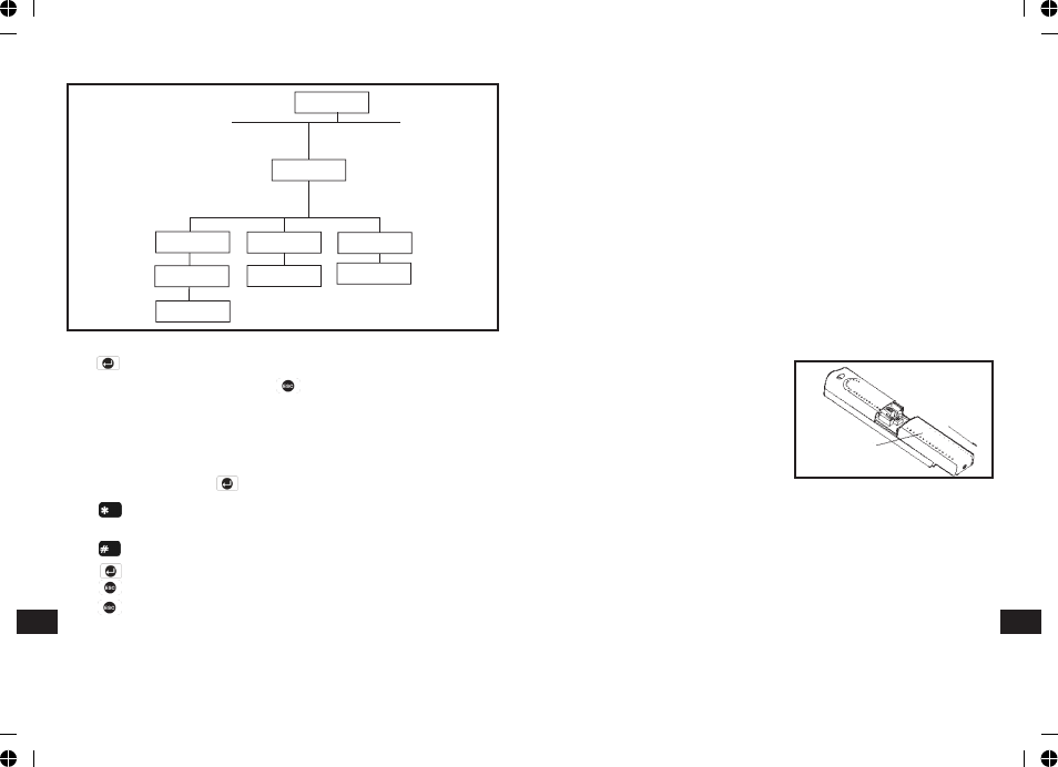
FULLY ARM SETUP
PROGRAM MODE
Code:
5. FULLY ARM
5-1 Exit Delay
xx xxx SEC
Select
ON->* OFF->#
Input
(1-250) Secs.
Select
ON->* OFF->#
5-2 Entry Delay
Beep: xxx
Select
ON-> OFF->#
5-3 Exit Delay
Beep: xxx
EN
EN