ELRO HA68S Multi-zone professional alarm system USERS MANUAL User Manual
Page 15
-13-
-52-
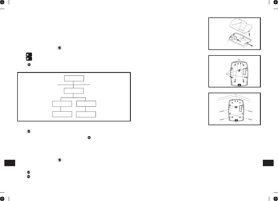
INSTALLING THE PIR DETECTORS
Ensure that the system is in Test Mode.
1. Undo and remove the fixing screw from
the bottom edge of the PIR. Carefully
pull the bottom edge of the detector
away from the rear cover and then
slide down to release the top clips.
2. Carefully drill out the required mounting
holes in the rear cover using 3mm drill
according to whether the unit is being
mounted in a corner or against a flat
wall.
Note: Using 1st mounting hole to fulfill
corner mounting installation, while 2nd
mounting hole for flat wall installation.
3. Using the rear cover as a template,
mark the positions of the fixing holes
on the wall.
4. Fix the rear cover to the wall using the
two 18mm No.4 screws and 25mm wall
plugs, (a 5mm hole will be required for
the wall plugs). Do not over-tighten the
fixing screws as this may distort or
damage the cover.
5. Configure the PIR detector as described below. Remember that on initial
installation that the device needs to be tested and should therefore be set in
Walk Test Mode.
6. Check that the detector PCB is located and set in the correct position to
provide the required detection range. To adjust the PCB position, simply slide
it up or down ensuring that the location legs are aligned with the required
position number marked on the board.
7. To refit the PIR detector to the rear cover and locate the clips in the top edge
into the rear cover. Push the lower edge of the detector into place and refit
the fixing screw in the bottom edge of the PIR to secure in position. Do not
over-tighten the fixing screws as this may damage the casing.
Fixing screw
Rear Cover
2nd Mounting Hole
Positions
1st
Hole Positions
Mounting
Corner mounting
Scroll through the menu until ‘8 TIME & DATE SETUP’ is displayed and
press .
Note: After configuring the Time and Date press to return to the top level
programming menu.
DATE
Scroll through the menu until ‘8-1 Date’ is displayed. The current setting will
also be displayed.
To change the setting press .
Enter the date in the format ‘dd/mm/yy’.
Press to save and exit, or
Press to exit without saving.
EXIT DELAY BEEP
This controls the warning beep which operates during the Exit Delay period
when Partial Arm 2 is initiated.
Default setting: ON
Scroll through the menu until ‘7-3 Exit Delay Beep’ is displayed. The current
setting will also be displayed.
To change the setting press .
Press to enable the Exit-delay beep, or
Press to disable the Exit-delay beep.
Press to return to top level Partial Arm 2 Setup menu.
TIME & DATE SETUP
PROGRAM MODE
Code:
8. Time & Date
8-1 Date
dd/mm/yy
DD/MM/YY
xx/xx/xx xxx
8-2 Time
hh/mm/ss
HH/MM/SS
xx::xx:xx
EN
EN