ELRO HA68S Multi-zone professional alarm system USERS MANUAL User Manual
Page 17
-15-
-50-
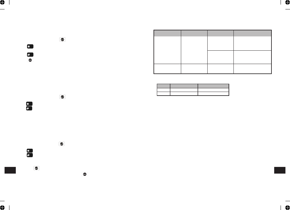
On/Off Selection DIP1 of SW2
DIP2 of SW2
Trigger reaction of LED
ON
Walk Test mode
High Sensitivity
LED will be on once.
It implies high
sensitivity.
Low Sensitivity
LED will flash twice.
It implies low
sensitivity.
OFF
Normal mode
High/Low
LED does not light up.
Sensitivity
3. The setting of the DIP1 & DIP2 of SW2 can be distinguished from the LED
indication as follows:
In summary, the setting of DIP1 & DIP2 of SW2 is concluded as below:
4. Connect the 1/2 3.6V Lithium battery to the battery spring.
Note: When the battery is connected, the LED behind the lens will flash for 2-
3 minutes as warming-up duration until the PIR has stabilized when the LED
will then stop flashing and turn OFF.
5. In normal mode, remove the rear cover of the PIR detector. The Detector’s
LED will illuminate and the Control Panel should beep. It is because the
tamper switch fitted on the Detector has been activated.
6. When the Detector is fully installed i.e. battery cover is refitted; the Detector
will not detect movement for approximately 2 minutes after each activation.
(This feature is present to conserve battery power and maximize the battery
life).
7. In order to communicate with the Control Panel, the ID code of the Detector
needs to be learned by the Control Panel. By pressing the tamper switch
located adjacent to the PCB on the Detector will emit the ID code to the
Control Panel instantly, subject to the Control Panel being set at the Zone
setup mode.
TESTING THE PIR DETECTORS
Ensure that the system is in Test Mode.
With the PIR detector set in Test mode and mounted in position on the wall,
allow 2-3 minutes for the detector to stabilize before commencing the Walk Test.
SW2
DIP1
DIP2
ON
Walk Test Mode
High sensitivity
OFF
Normal Mode
Low sensitivity
EXIT DELAY
Scroll through the menu until ‘6-1 Exit Delay’ is displayed. The current setting
will also be displayed.
Default setting: ON
To change the setting press .
Press to enable the Exit delay and enter the required exit delay period
(1-250s), or
Press to disable the Exit delay.
Press to return to top level Partial Arm 1 Setup menu.
ENTRY DELAY BEEP
This controls the warning beep which operates during the Entry Delay period
when Partial Arm 1 is active.
Default setting: ON
Scroll through the menu until ‘6-2 Entry Delay Beep’ is displayed. The current
setting will also be displayed.
To change the setting press .
Press to enable the Entry-delay beep, or
Press to disable the Entry-delay beep.
EXIT DELAY BEEP
This controls the warning beep which operates during the Exit Delay period when
Partial Arm 1 is initiated.
Default setting: ON
Scroll through the menu until ‘6-3 Exit Delay Beep’ is displayed. The current
setting will also be displayed.
To change the setting press .
Press to enable the Exit-delay beep, or
Press to disable the Exit-delay beep.
PARTIAL ARM 2 SETUP
Scroll through the programming menu until ‘7. PARTIAL ARM 2’ is displayed
and press .
Note: After configuring Partial Arm 2 press to return to the top level
programming menu.
EN
EN