ELRO HA68S Multi-zone professional alarm system USERS MANUAL User Manual
Page 22
CALL ATTEMPTS
This sets the maximum number of times that the dialer will attempt to contact
the central monitoring station.
If the dialer contacts to the central monitoring station once successfully, it will
stop dialing.
Default setting: 3
Scroll through the menu until ‘:3 Call Attempts’ is displayed. The current
setting will also be displayed.
To change the setting press .
Enter the required number (1-5).
Press to save and exit, or
Press to exit without saving.
ARM/DISARM BY USER
This determines when user makes a selection for disarming (Open) or arming
(Close) the system, an event code 401 is needed to be sent to the central
monitoring station. When setting to ‘On’, an event code 401 will be emitted,
setting to ‘Off’, an event code 401 won’t be emitted.
Default setting: Off
Scroll through the menu until ‘:4 ARM/DISARM By User’ is displayed. The
current setting will also be displayed.
To change the setting press .
Press to commence sending the event code.
Press to commence not sending the event code.
REMOTE SYSTEM CONTROL SETUP
Scroll through the manual until ‘4-3 Remote TEL Control Setup’ is displayed
and press .
Note: After completing the Remote Tel Control Setup, press to return to
the top level programming menu.
-45-
-20-
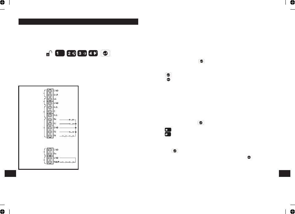
EXTERNAL CONNECTIONS
The Control Unit incorporates a terminal block for connection of hard-wired
Zones (33-36), Siren or Telephone Dialer unit. The connection terminal block is
located inside the Control Panel behind the front cover.
To access the terminal block Press
this puts the system into Test Mode and prevents an alarm occurring. Undo the
two fixing screws on the top edge of the Control Panel and open the front cover.
Before making any connections, ensure that the memory jumper link P1 is in
the ‘OFF’ position and then remove the DC power jack and disconnect one of the
back-up batteries.
Hardwired zone and tamper switches
should be Volt free and Normally
Closed, with the contacts opening in
order to initiate an alarm.
Note: Jumper link P51 should be
fitted into the ON position only if the
external hardwired tamper circuit is
used, otherwise it must be in the OFF
position.
After making your external
connections reconnect the power
supply and Back-up Battery. Then
close the Control Panel cover and
tighten the fixing screws on the top
edge of the Control Panel.
Terminal Block
EN
EN
Hardwire siren termina,there
is output voltagein OUT
position when alarm mode
(siren setting in ON mode)
DC power output terminal
V+ has power voltage output
Relay output terminal,
accept other N.C. or N.O.
devices
Battery power pack input,
option 12V DC battery input
to increase system stand by
life time
Negative tamper return,
normal close, system can be
detected once circuit close
Hard-wired zones for trigger
onput terminal, use standard
hard wire magnetic, there
are 4 sets of hard-wired
zones: T1(zone7), T2(zone8)
T3(zone9), T4 (zone10)