ELRO HA68S Multi-zone professional alarm system USERS MANUAL User Manual
Page 18
-49-
-16-
MAGNETIC CONTACT DETECTOR(S)
The Magnetic contact consists of two parts; a Detector and a Magnet. They are
designed to be fitted to doors or windows with the Magnet mounted on the
opening part and the Detector mounted on the fixed frame. Opening the
protected door/window will remove the magnetic field, trigger the Detector and
generate an alarm condition, (if the system is armed and the alarm zone
active).
The Detector is powered by one 3.6V 1/2 AA size Lithium cells which under
normal conditions will have typical life in excess of 5 years. Under normal
battery conditions with battery cover fitted the LED on the Detector will not
illuminate when the Detector is triggered, (unless in test mode). However, under
low battery conditions this LED will be illuminated when the detector is
triggered. When this occurs the battery should be replaced as soon as possible.
1. Use the and buttons to scroll through the menu until ‘WALK TEST’
is displayed.
Press to activate Walk Test. ‘Walk Test Waiting…’ will be displayed.
2. Walk into and move slowly around the protected area, each time the detector
senses movement the LED behind the lens will flash. In addition, the Control
Panel will beep to indicate that the alarm signal has been received and the
identity of the zone that the detector is configured for will be displayed.
If necessary adjust the detection range by changing the mounting position of
the PCB within the PIR housing.
Note: In normal operation, the LED behind the PIR lens will not flash on
movement detection, (unless the battery is low).
If necessary re-adjust the detection pattern by changing the mounting
position of the PCB within the PIR housing.
3. Remove the back cover of the PIR detector. The Control Panel should beep
and display ‘PIR Detector Tamper’ to show that the detector’s tamper switch
has been activated.
4. Press to return to the top level menu of TEST MODE.
5. Reconfigure the PIR Detector for normal mode by setting DIP1 of SW2 to OFF
and refit in position.
Note: When the detector is fully installed i.e. battery cover is refitted; the
unit will not detect movement for approximately 2 minutes after each
activation. (This feature is present to conserve battery power and maximize
the battery life).
Default setting: ON
Scroll through the menu until ‘5-2 Entry Delay Beep’ is displayed.
The current setting will also be displayed.
To change the setting press .
Press to enable the Entry-delay beep, or
Press to disable the Entry-delay beep.
EXIT DELAY BEEP
This controls the warning beep which operates during the Exit Delay period
when Full Arm is initiated.
Default setting: ON
Scroll through the menu until ‘5-3 Exit Delay Beep’ is displayed. The current
setting will also be displayed.
To change the setting press .
Press to enable the Exit-delay beep, or
Press to disable the Exit-delay beep.
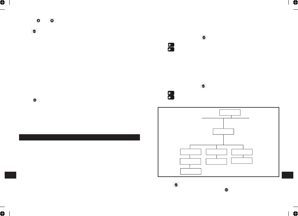
PARTIAL ARM 1 SETUP
PROGRAM MODE
Code:
6. PARTIAL ARM 1
6-1Exit Delay
xx xxx SEC
Select
ON->* OFF->#
Input
(1-250) Secs
Select
ON->* OFF->#
6-2 Entry Delay
Beep: xxx
6-3 Exit Delay
Beep: xxx
Scroll through the programming menu until ‘6. PARTIAL ARM 1’ is displayed
and press .
Note: After configuring Partial Arm 1 press to return to the top level
programming menu.
EN
EN
Select
ON-> OFF->#