Burkert Type 8750 User Manual
Page 43
43
DeviceNet start-up
Typ 8750
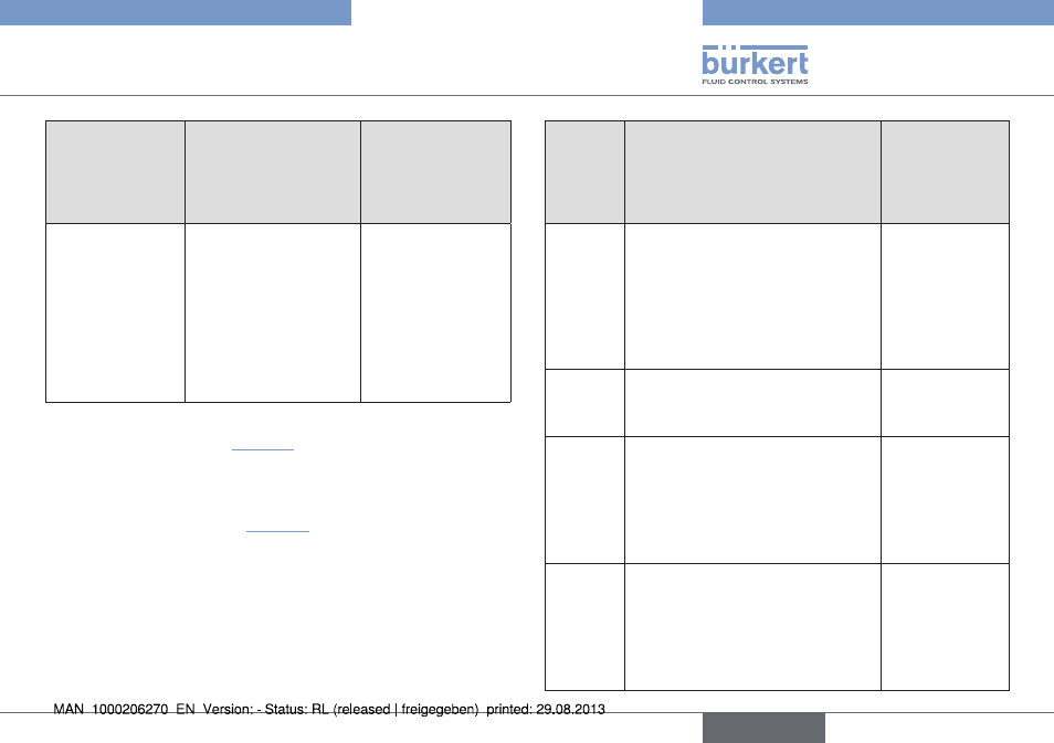
name
address of data
attribute of the
assemblies for
read access. class,
instance, attributes
format of the data
attribute
PV+POS+ERR+
PCON+P1
4, 9, 3
Byte 0: PV low
Byte 1: PV high
Byte 2: POS low
Byte 3: POS high
Byte 4: ERR
Byte 5: PCON
active
Byte 6: P1 low
Byte 7: P2 low
Tab. 26: Static Input Assemblies, DeviceNet
The addresses indicated in “Tab. 26” can be used as a path
statement for the Produced Connection Path attribute of an
I/O connection.
This I/O connection can be used to transfer the attributes described
in more detail in the following “Tab. 27” as input process data.
Nevertheless, by using this address data, the attributes combined
in the assemblies can also be accessed acyclically at any time via
Explicit Messages.
name
description of the input data
attributes
attribute
address class,
instance,
attribute; data
type, length
POS
Actual position
Actual value of process controller
as ‰.
Value range 0 – 1000.
However, values <0 or >1000 are
also possible if e.g.
X.TUNE has not
run through correctly.
111, 1, 59;
INT, 2 byte
CMD
Set-point position
Set-point value of positioner as ‰.
Value range 0 – 1000.
111, 1, 58;
UINT, 2 byte
PV
Process actual value (process value)
Actual value of process controller
in physical unit (as set in the
menu
P.CO INP or P.CO SCAL),
max. value range -999 – 9999,
depending on internal scaling.
120, 1, 3;
INT, 2 byte
SP
Process set-point value
Set-point value of process con-
troller in physical unit (as set in the
menu
P.CO INP or P.CO SCAL),
max. value range -999 – 9999,
depending on internal scaling.
120, 1, 2;
INT, 2 byte
english