Burkert Type 8750 User Manual
Page 21
21
Electrical installation
Typ 8750
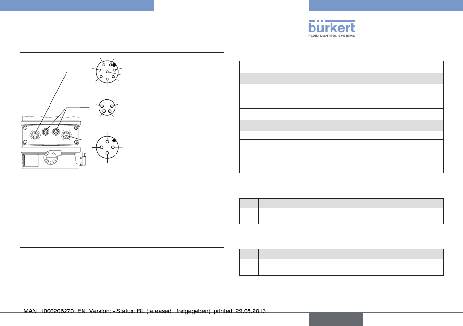
circular plug m12, 4-pole
circular plug m12, 8-pole
Operating voltage
Input signals from the control
center
Output signals from the control
center (optional)
1
2
3
4
5
6
7
8
1
2
3
4
1
2
4
3
Pressure sensor P1, P2
circular plug m8, 4-pole
Fig. 12: Connection with 24 V DC circular plug-in connector
4)
The indicated colors refer to the connecting cable available as an
accessory (919061).
5)
The indicated colors refer to the connecting cable available as an
accessory (92903474).
6)
The indicated colors refer to the connecting cable available as an
accessory (918038).
Circular plug M12, 8-pole
Set-point value, binary input
pin
wire color
4)
assignment
8
red
Set-point value + (0/4 – 20 mA / 0 – 5/10 V)
7
blue
Set-point value GND
1
white
Binary input +
Input/output signals - option only
pin
wire color
4)
assignment
6
pink
Analog position feedback +
5
gray
Analog position feedback GND
4
yellow
Binary output 1
3
green
Binary output 2
2
brown
Binary outputs GND
Tab. 7: Circular plug M12, 8-pole
Circular plug M8, 4-pole (pressure sensor)
pin
wire color
5)
assignment
1
brown
+ 24 V pressure sensor power supply
2
white
4 – 20 mA output from pressure sensor
Tab. 8: Circular plug M8, 4-pole (pressure sensor)
Circular plug M12, 4-pole (operating voltage)
pin
wire color
6)
assignment
1
brown
Operating voltage +
24 V DC
3
blue
Operating voltage
GND
Tab. 9: Circular plug M12, 4-pole (operating voltage)
english