Pressure loss specifications, English – Burkert Type 8712 User Manual
Page 21
21
Technicaldata
Type 8626, 8712
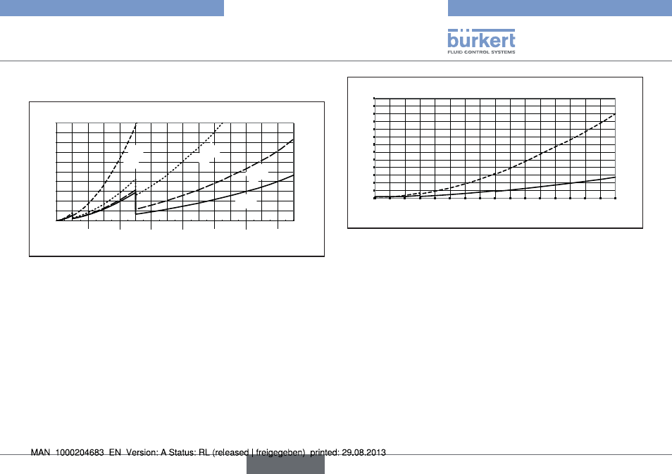
6.6.3. pressure loss specifications
Q [l
N
/min]
∆p [mbar]
0
20
40
60
80
100
120
140
160
180
200
0 100
200
300
400
500
600
700
800
900
1000
1100
1200
1300
1400
1500
1/4''
3/8''
1/2''
3/4''
Fig. 18: Pressure loss diagram (ref. air, with 250 µm inlet filter),
type 8006
The characteristic diagram shows the air pressure loss in the device
for 3 different bases (up to 100 Nl/min, from 100 to 500 Nl/min,
from 500 to 1500 Nl/min) and 4 different connections (1/4'', 1/2'',
3/4'' and 3/8'').
For determining the pressure loss with another gas first calculate the
equivalent air flow-rate of the other gas.
0
10
20
30
40
50
60
70
80
90
100
110
120
130
0
5 10 15 20 25 30 35 40 45 50 55 60 65 70 75 80
Q [l
N
/min]
∆p [mbar]
flanges
1/4''
Fig. 19: Pressure loss diagram (ref. air, with 250 µm inlet filter),
type 8702
The characteristic diagram shows the air pressure loss in the
device for versions with flange connections and versions with 1/4''
connections.
For determining the pressure loss with another gas first calculate
the equivalent air flow-rate of the other gas and respect the fluidics
needed with the other gas.
English