Camera installation, Connection – eLine Technology SIP-FB User Manual
Page 8
5
6
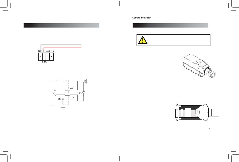
3. CAMERA INSTALLATION
Make sure to follow the correct polarity if connecting
the camera to DC power. Polarity is marked on the
power connector.
1.
Box Camera requires only the
correct mounting to be applied
to the camera
Standard installation can be from bottom
Or can be made from the top of camera/
2.
Use the included connection
to attach the bottom
installation connections block,
using the provided small
screws to attach to base of
camera.
3.
Connect camera Lens, use the
BNC connector for a fast live
video output view to adjust and
focus camera.
4.
Optional use the back focus
adjustment Ring if required to fit
lens so focus position is correct.
Connection
2. CONNECTION
Alarm input connection as below diagram:
(-)GND
(+)DC5-12V
Alarm output is in on-off (No voltage), outside power is needed while connection alarm.
Outside power must be within DC12V and 300mA while connection DC power.
1. RJ45 Network Interface: Connect to a router or switch on your network
using RJ45 Ethernet cable (Cat5e or better). 100Mhz connection. PoE
supported (class 3 PoE switch required).
2. Audio Input (3.5mm): Connect to a self-powered microphone for listen-
in audio.
3. Audio Output (3.5mm): Connect to an amplifier or self-powered speaker
for intercom/2-way audio.
4. DC12V (1A): 12V DC power input terminal. Make sure to follow correct
polarity (+/-) marked on the power connector when connecting to power.
•
Minimum Power Requirement: 450mA / 5.4W.
eLineTechnology