Cabling scenarios diagram, Cabling scenarios diagram -11, Connecting to the network – Asante Technologies 5212 User Manual
Page 33: Page 2-11
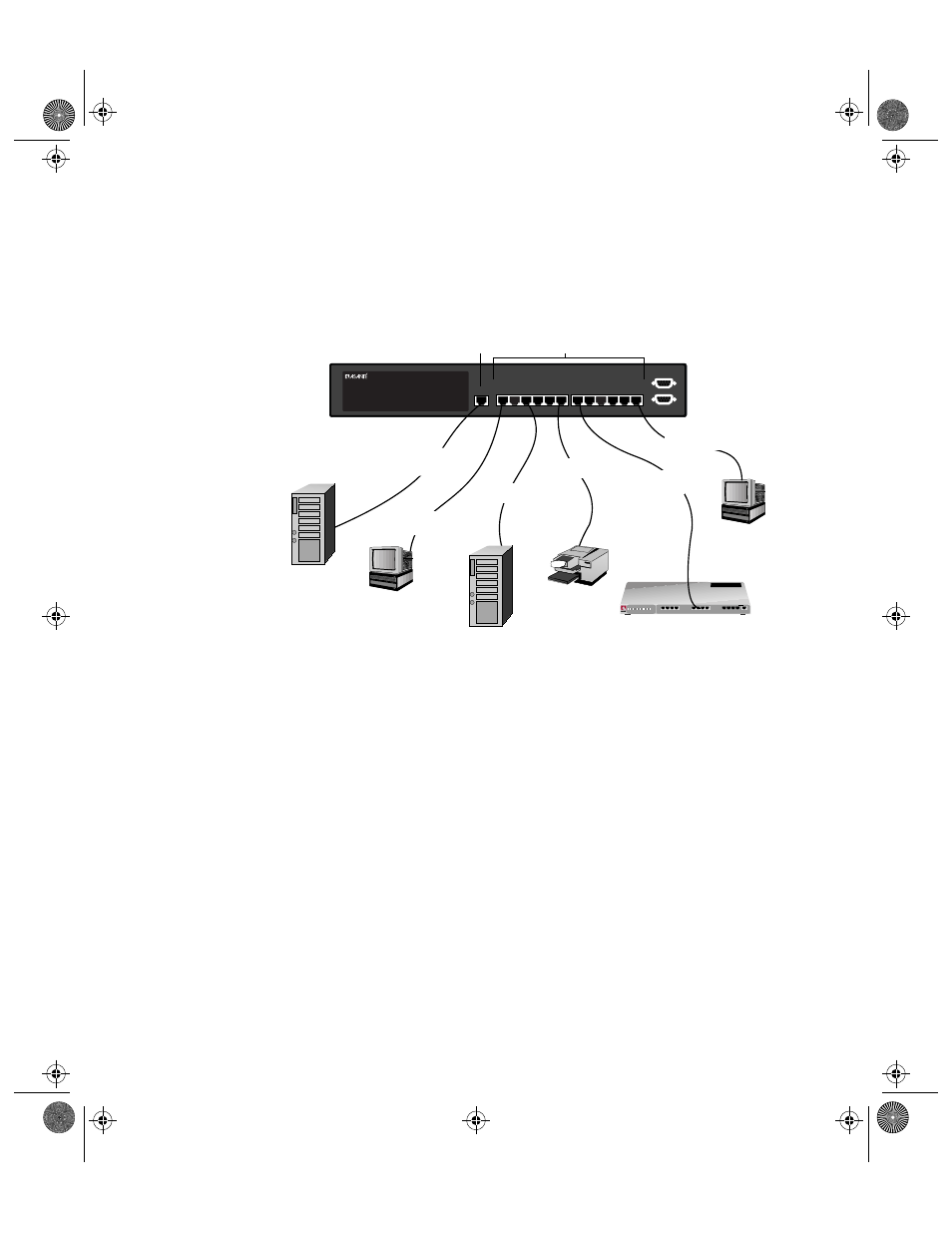
Connecting to the Network
Page 2-11
Cabling
Scenarios
Diagram
The following diagram illustrates some of the various cabling
scenarios available with the IntraSwitch 5212.
Figure 2-7
IntraSwitch 5212 cabling scenarios
IntraSwitch 5212
POWER
100 Mbps
Max Util
FDP
Data
Link
10/100 1 2 3 4 5 6 7 8 9 10 11 12 MII
10/100
Console
RS-232
7
8
9
10
11
12
1
2
3
4
5
6
10Base-T
Workstation
Category 5
straight-through cable
(100m max. length)
100Base-TX
Server
straight-through cable
(100m max. length)
Printer
1
2
3
4
5
6
7
8
9
10
11
12
100BASE-TX Ports
4
3
2
1
5
6
7
8
Col
Pwr
9 10 11 12
Partition
Link/Receive
Uplink
or
AsantéFAST 100 TX Hub
Remove Before Stacking
Hub
cross-over cable
(100max. length)
straight-through cable
(100m max. length)
10Base-T
Workstation
10Base-T
Server
straight-through cable
(100m max. length)
10Base-T ports: require
Category 3, 4, or 5 cable
10/100 port: requires
Category 5 cable
straight-through cable
(100max. length)
book Page 11 Monday, March 2, 1998 4:27 PM