Appendix g: wiring to m800 ecu, M800 and br2, 40 appendices – MoTeC MDD User Manual
Page 42
40 Appendices
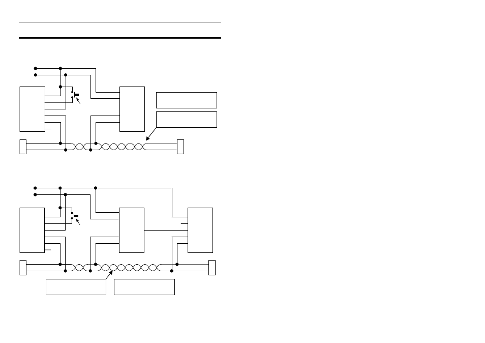
Appendix G: Wiring to M800 ECU
The wiring below shows how to connect the MDD to the M800.
For detail on CAN Bus wiring refer to Appendix D: General CAN Bus Wiring.
1
BAT-
MDD
M800 / M880
2
RX
3
BAT+
4
CAN-LO
CAN-LO
B24 / 47
5
CAN-HI
CAN-HI
B23 / 48
CAN-LO
CAN-HI
10
0R
10
0R
6
BAT-
BAT+
BAT-
BAT+
CAN-LO
CAN-HI
Display Mode Button
See the General CAN
Bus Wiring for detail
Note: CAN Cable
connector not shown
M800 and BR2
The diagram below includes a BR2 Lap Beacon receiver
1
BAT-
MDD
M800 / M880
2
RX
3
BAT+
4
CAN-LO
CAN-LO
B24 / 47
5
CAN-HI
CAN-HI
B23 / 48
CAN-LO
CAN-HI
10
0R
10
0R
8V A13 / 2
6
BAT-
BAT+
1
BAT-
BR2
2
3
8V Power
4
CAN-LO
5
CAN-HI
BAT-
BAT+
CAN-LO
CAN-HI
Display Mode Button
See the General CAN
Bus Wiring for details
Note: CAN Cable
connector not shown