Appendix e: wiring to m4 / m48 ecu, M4/48 and br2, 38 appendices – MoTeC MDD User Manual
Page 40
38 Appendices
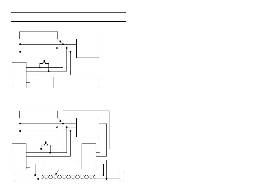
Appendix E: Wiring to M4 / M48 ECU
The diagram below shows how to connect the MDD to an M4 or M48.
1
BAT-
MDD
2
RX
3
BAT+
4
CAN-LO
5
CAN-HI
6
BAT-
BAT+
Display Mode Button
M4 / M48
Tx
11
BAT+
25
BAT-
1
Note: Splice MDD Power
and Ground close to ECU
Note1: M4 (Pre M4e) and all M48
will require splicing with the 9pin
PC communications connection
Note 1
M4/48 and BR2
The diagram below includes a BR2 Lap Beacon receiver
For detail on CAN Bus wiring refer to Appendix D: General CAN Bus Wiring.
1
BAT-
MDD
BR2
2
RX
3
BAT+
4
CAN-LO
CAN-LO
4
5
CAN-HI
CAN-HI
5
CAN-LO
CAN-HI
100
R
100R
6
BAT-
BAT+
BAT-
8V Power
1
3
2
Display Mode Button
M4 / M48
Tx
11
BAT+
25
BAT-
1
8V
26
CAN-LO
CAN-HI
Note: Splice MDD Power
and Ground close to ECU
See the General CAN
Bus Wiring for details