10 rs-232 configuration, 11 gpib address, 12 gpib connections – B&K Precision 4034 - Manual User Manual
Page 14
14
DB-9 pin Name
Note
1
2
3
4
5
6
7
8
9
-
TXD
RXD
-
GND
-
RTS
CRS
-
-
Transmit Data
Receive Data
-
Signal ground
-
Request to Send
Clear to send
-
*Note: Use a Null-modem or cross over cable (pin 2 and 3 switched) in order to communicate with instrument.
2.10 RS-232 Configuration
The instrument use 8 data bits, 1 stop bit, no parity and baud rate selectable from 2400 to 115K (2400, 4800,
9600, 19200, 38400, 57600, 115200). By default, the instrument is set at 19200-8-N-1.
Note: If 115K baudrate speed is used, ensure that the RS232 cable is short and can support this speed. Otherwise,
there may be some instability and intermittent data transmission failure between the interfacing computer and
the instrument.
2.11 GPIB Address
The address can be changed from the front panel by using the "UTILITY" menu.
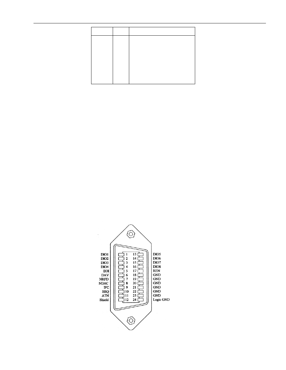
2.12 GPIB Connections
The rear panel GPIB connector is an AMPHENOL 57-10240 or equivalent, and connects to a standard IEEE-488
bus cable connector. The GPIB line screens are not isolated from chassis and signal ground.