Setting the discharge volume, Operation, Analog mode – Pump Solutions Group PZiG Series User Manual
Page 20: Setting scaling in the analog mode
19
Operation
In the analog mode, analog signals from an external
device are received, and automatic operation is per-
formed within the range 0 to 300 spm according to the
setting values (set point (SP), and proportional band
(PB)).
First, perform scaling according to the application of
this pump, and then set the set point. Set the ramp of
the stroke with respect to analog output as a propor-
tional band (increment value: 1 to 999%, and decre-
ment value: -1 to -999%), and linearly vary the number
of strokes according to the analog input signal from the
external device.
●Relationship between scaling and set point/pro-
portional band
Analog Mode
Setting the Discharge Volume
Scaling
Scaling
Set point
setting
Set point
setting
Proportional
band setting
Proportional
band setting
Set the set point
(unit and range)
according to the
desired scaling
range.
When the scal-
ing range is
changed, the
set point also
is changed in
proportion to
that change.
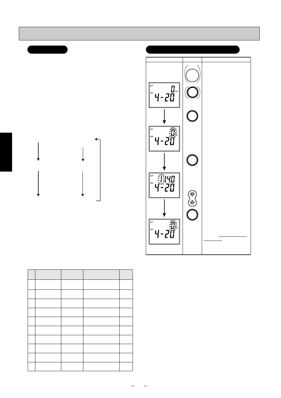
Display
Operation
Explanation
If the pump is operating, press the
STOP key to stop pump operation.
If the screen on the left is not
displayed, press the MODE key until
it is displayed.
Press the FUNC key to enter the
scaling change screen.
The screen on the left shows that
scaling No.1: 0.0 to 14.0 is currently
selected.
For details on scaling selection
details, refer to the "List of scaling
selections."
Press the SET key with pump
operation stopped to enter the set
point setting screen.
Press the UP/DOWN key to select
scaling.
Press the FUNC key to apply the
selected details.
When a scaling No. has been
changed to a different No., the scale
of the set point is automatically
changed.
Next, set the set point.
Proceed to "Set the set point by the
UP/DOWN key" on the 11th line of
"Setting Set Point/Proportional Band
in the Analog Mode" on the following
page.
START
STOP
MODE
FUNC
FUNC
SET
RESET
No.
Appli
cation
0
Stan-
dard
1
pH
6
Residual
chlorine
7
Residual
chlorine
8
Residual
chlorine
Scaling
Range
Indication on
Operation Panel
Settable Unit
0 to 100
0 100
%
1 step (Step 1)
0.0 to 14.0
1 14.0
0.1 step (Step 0.1)
2
0.00 to 1.00
2 1.00
0.01 step (Step 0.01)
Residual
chlorine
3
0.00 to 2.00
3 2.00
0.01 step (Step 0.01)
Residual
chlorine
4
0.00 to 5.00
4 5.00
0.01 step (Step 0.01)
Residual
chlorine
5
0.0 to 10.0
5 10.0
0.1 step (Step 0.1)
Residual
chlorine
0.0 to 20.0
6 20.0
0.1 step (Step 0.1)
0.0 to 50.0
7 50.0
0.1 step (Step 0.1)
0 to 100
8 100
1 step (Step 1)
9
0 to 200
9 200
1 step (Step 1)
Residual
chlorine
●Scaling
Normally, perform scaling before setting the set point.
Set points matched to the target application can be set
by performing scaling. Scaling details can also be
changed after the set point is set. However, in this
case, the target value is automatically changed accord-
ing to the newly changed scaling details.
The following summarizes the scaling ranges that can
be selected.
●List of scaling selections
* On the operation panel, the selected scaling No. and
the maximum value of the scaling range are displayed.
Setting Scaling in the Analog Mode
05-45_PZiG Series(2)English 06.8.4 9:39 AM y [ W 19