Sync polarity jumpers, Video clamping jumper, Sync polarity jumpers video clamping jumper – Extron Electronics RGB 203 Rxi User Guide User Manual
Page 13
3.
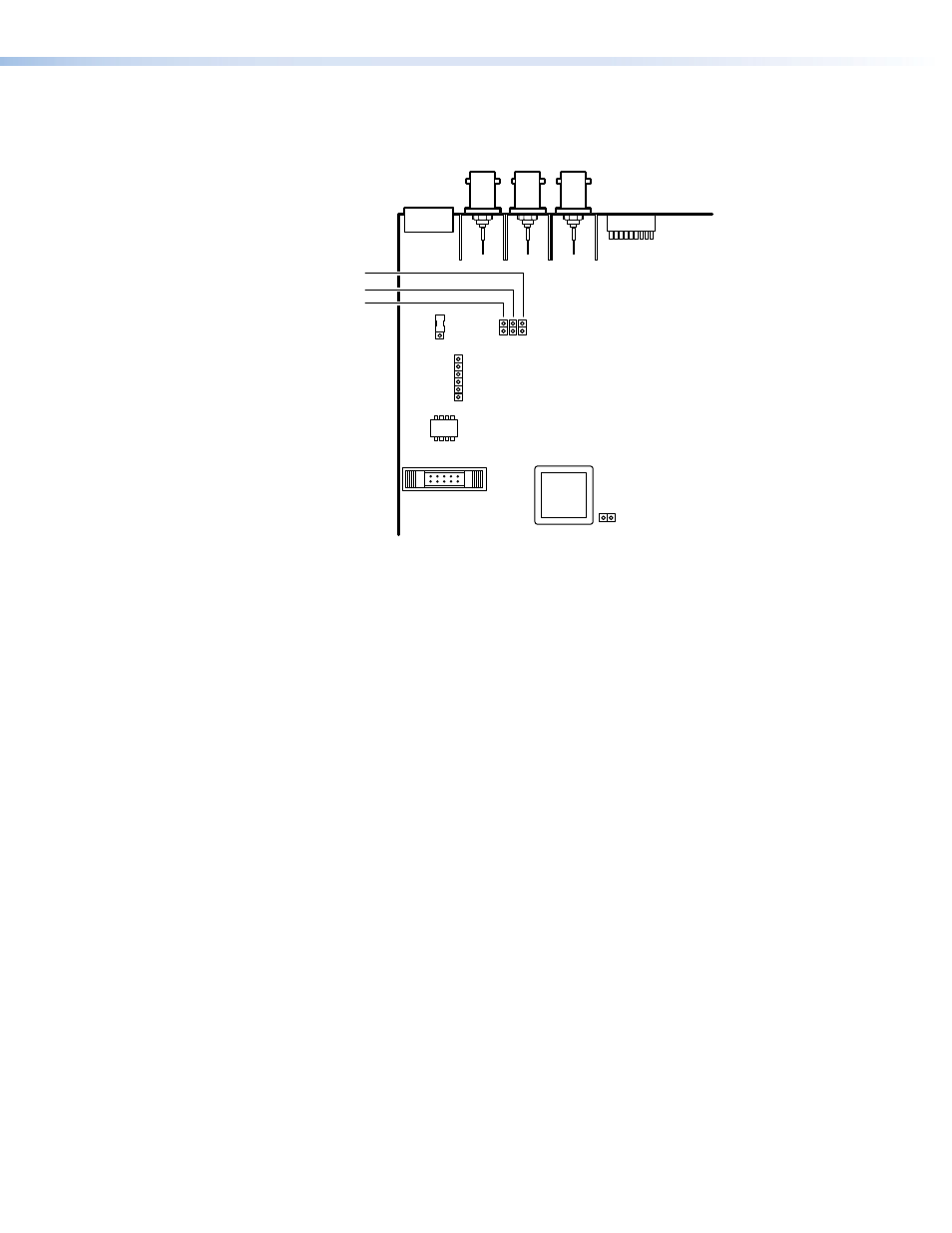
Configure the interface as desired (see
and
below). Figure 7 shows all of the user-serviceable components.
J27
J23
RS-232
Connector
J11
3
2
1
1
1
J28
J7
V Sync
J6
H Sync
J20 Enable
Sync
Rear
Figure 7.
RGB 203 Rxi Internal Jumper Locations
4.
Replace the cover and reinstall the screws.
Sync Polarity Jumpers
The interface is factory configured for the output sync to follow the input sync. To force
positive or negative sync, reconfigure the jumpers as follows:
1.
Locate jumper blocks J6, J7, and J20 on the printed circuit board (see figure 7).
2.
For sync follow (output sync polarity identical to the input sync), remove the
jumper from block J20.
3.
For positive or negative sync, install a jumper in block J20 and configure J6 and J7 as
follows:
a.
Vertical sync — For positive sync, install a jumper in jumper block J7. For negative
sync, remove the jumper from jumper block J7.
b.
Horizontal sync — For positive sync, install a jumper in jumper block J6. For negative
sync, remove the jumper from jumper block J6.
Video Clamping Jumper
The interface is factory configured to clamp the sync timing to the back porch. To clamp the
sync timing to the tip of the sync pulse, reconfigure the jumper as follows:
1.
Locate J11 on the printed circuit board (see figure 7).
2.
Set the jumper between pins 1 and 2 for sync timing clamped to the back porch.
or
Set the jumper between pins 2 and 3 for sync timing clamped to the sync tip.
RGB 203 Rxi • Configuration
7