Installation, cont’d – Extron Electronics MLM-WB+ User Guide User Manual
Page 14
Installation, cont’d
MLM-WB • Installation
2-8
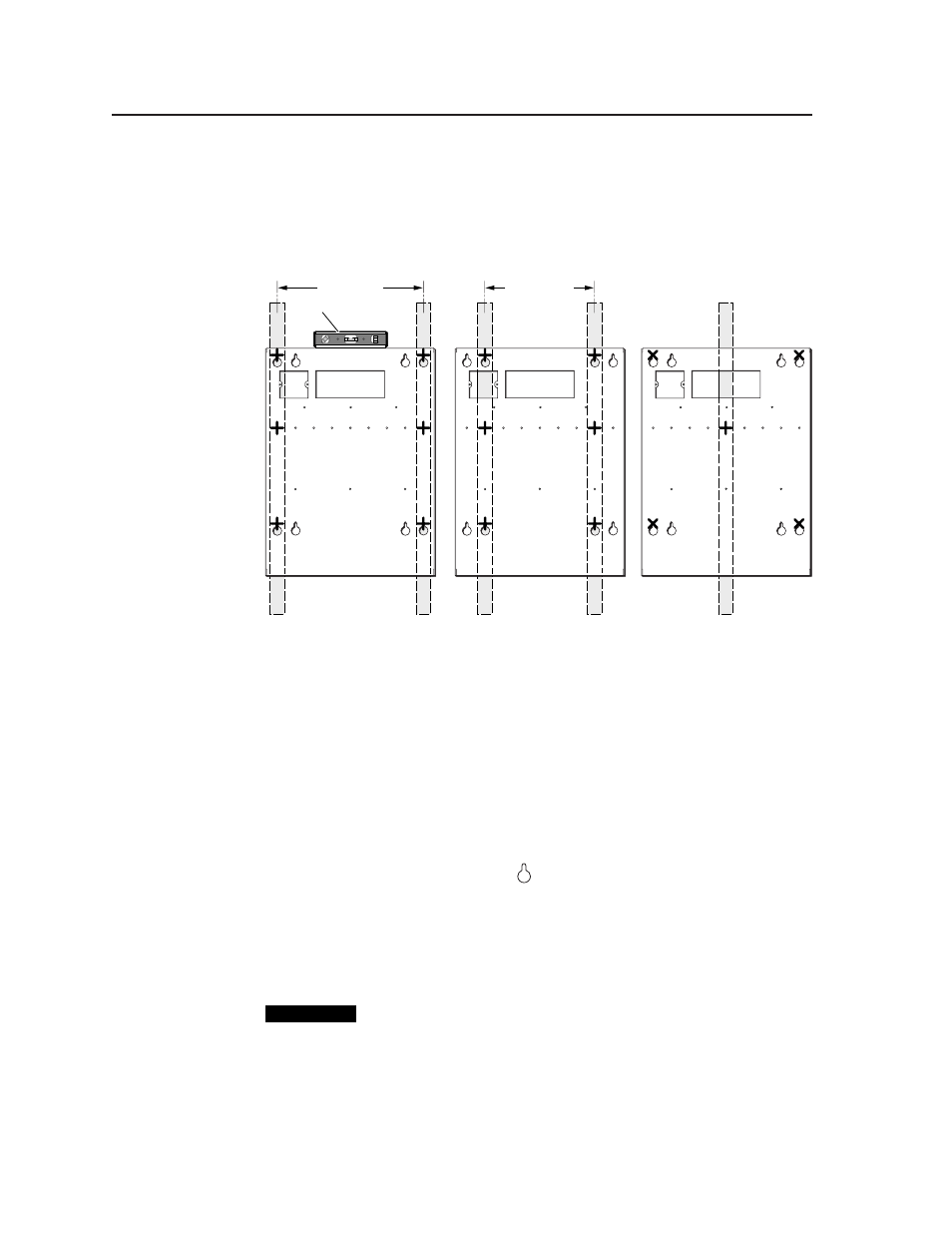
the enclosure and observe the bubble in the horizontal tube. It will be in the
center of the tube when the enclosure is level.)
•
If two wall studs are accessible
where the MLM-WB will be installed,
align the mounting holes with the studs, and mark at least six locations
for self-tapping metal/wood screws, as shown (as + marks) in the
pictures below at left and center.
16" (40.6 cm)
12" (30.5 cm)
Level
•
If only one wall stud is accessible
, align the vertical center of the box
with the stud, and mark center hole location(s) (over the stud, shown as
+
marks)) for metal/wood screw installation. Mark additional mounting
hole locations (shown as “X” marks) to add toggle bolts to increase the
installation’s stability and strength. See the rightmost picture on page 2-7.
4.
Set the enclosure out of the way.
5.
Drill pilot holes in the wall at the locations you marked in step three.
•
For wood/metal screws, make the holes up to 3/16” in diameter, 1.75”
(4.4 cm) deep.
•
For toggle bolts, make holes 11/16”(1.7 cm) wide through to the hollow part.
The figure on page 2-9 shows the steps required to install the toggle bolts.
6.
For each slotted mounting hole (
) for which you have drilled a pilot hole:
a.
Insert a provided wood/metal screw through a flat metal washer (1”,
2.5 cm outer diameter; 0.25”, 0.6 cm inner diameter).
b.
Insert the screw into the pilot hole.
c.
Securely fasten each screw (or toggle bolt) into the wall until a gap of
1/8” (3 mm) remains between the wall and the metal washer.
CAUTION
Hand screw the bolts into the wall. Do not use a power tool to screw in
toggle bolts. Power tools may create too much pressure, causing the
Toggle Kap’s plastic washer to break. The Toggle Kap will then fall into
the wall.