Lockit lacing brackets, Figure 12. lockit lacing bracket examples, Mps 601 • installation 9 – Extron Electronics MPS 601 User Guide User Manual
Page 15
-- A MAX
POWER
12V
1
2
B
A
3
4
5
6
INPUTS
MPS 601
CONTACT IN / TALLY OUT
HDMI
RGBHV
HDMI
HDMI
RS-232
G
C
1
3
5
2
4
6
T
T
C G
T
C G
G
C
T
T
C G
T
+V
C G
Tx Rx G
OUTPUT
REMOTE
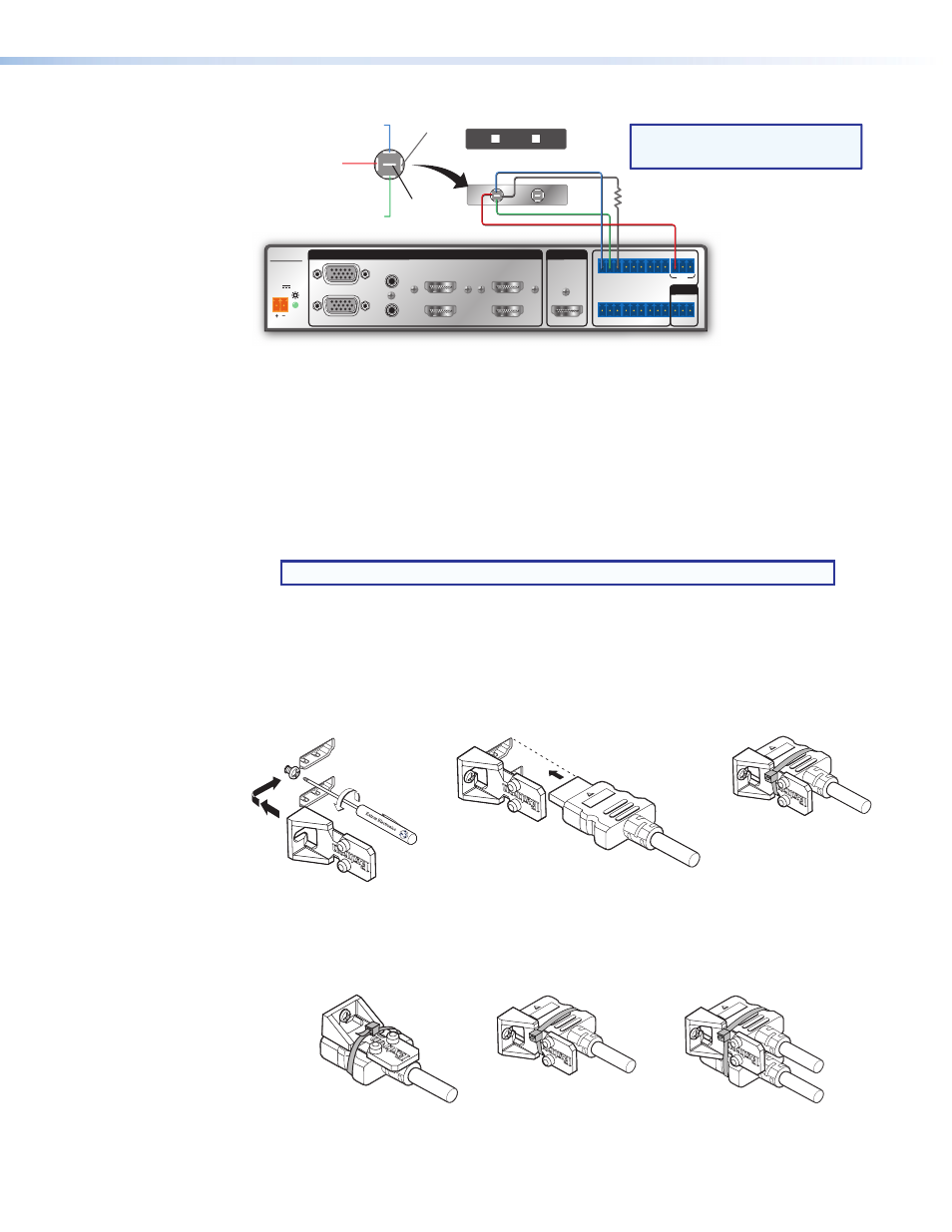
Two Contact Closure Switch AAP
PC
Solder Cups
Normally
Closed (NC)
Normally
Open (NO)
Common
Ground (C)
LED (-)
LED (+)
MPS 601
Resistor (R)
NOTE:
Determine and select the appropriate
current-limiting resistor, if needed.
Many button switches have the resistor built in.
Figure 10.
Contact Closure Application Diagram with Individual Switch
Lockit Lacing Brackets
The included Lockit lacing brackets secure the HDMI cables to the rear panel connectors
as shown. The configuration of the HDMI connectors on the MPS 601 rear panel require
using a top mount (HDMI output) and a stacked side mount (HDMI inputs 3 and 4 or
inputs 5 and 6) installation to secure the four inputs and single output.
1.
Loosen the HDMI connection mounting screw from the rear panel enough to allow the
LockIt lacing bracket to be placed over it.
NOTE: Do not remove the screw.
2.
Place the LockIt lacing bracket on the screw and against the HDMI connector, then
tighten the screw to secure the bracket.
3.
Plug the HDMI cable into the panel connection
4.
Loosely place the included tie wrap around the HDMI connector and LockIt lacing
bracket. Hold the connector securely against the lacing bracket and tighten the tie
wrap, then remove any excess length.
2
4
3
3
3
3
Side
Stacked
3
Top
HDM
I
1
1
2
2
3
3
4
4
Figure 11.
Lockit Lacing Bracket Installation
A single LockIt bracket can be used to secure two HDMI connectors in a stacked
configuration as shown below.
2
4
3
3
3
3
Side
Stacked
3
Top
HDM
I
1
1
2
2
3
3
4
4
Figure 12.
Lockit Lacing Bracket Examples
MPS 601 • Installation
9