Contact closure and tally output application, Diagrams, Rs-232 – Extron Electronics MPS 601 User Guide User Manual
Page 13: Figure 6. rs-232 connector wiring, Mps 601 • installation 7
H
RS-232 remote — 3-pole, 3.5 mm captive screw connector for a host computer
or a controller using Simple Instruction Set (SIS) or Windows-based control software
commands.
An IP Link driver allows Extron IPL and MediaLink devices to control the MPS 601 from
the RS-232 remote connector.
Ground (G)
Receive (Rx)
Transmit (Tx)
Bidirectional
RS-232
Device
Ground (G)
Receive (Rx)
Transmit (Tx)
Rx
Tx
G
Do not tin
the wires!
Figure 6.
RS-232 Connector Wiring
c
USB configuration port (front panel) — (see
Female USB mini-B jack used for configuration of the switcher and firmware upgrades
(see
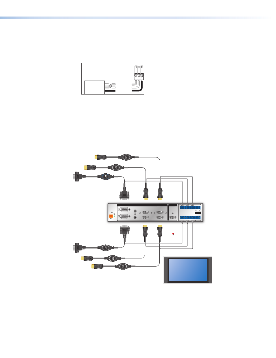
Contact Closure and Tally Output Application Diagrams
The following diagrams show examples of various connections using the contact enclosure
and tally output feature of the MPS 601.
-- A MAX
POWER
12V
1
2
B
A
3
4
5
6
INPUTS
MPS 601
CONTACT IN / TALLY OUT
HDMI
RGBHV
HDMI
HDMI
RS-232
G
C
1
3
5
2
4
6
T
T
C G
T
C G
G
C
T
T
C G
T
+V
C G
Tx Rx G
OUTPUT
REMOTE
VGA/HDMI “Show Me” Cables
MPS 601
Display
Contact
Closure
and Tally
HDMI Video and
Embedded Audio
Figure 7.
Contact Closure Application Diagram with Show Me Cables
MPS 601 • Installation
7