Front panel, Rear panel, Hardware setup – Extron Electronics IPL T PC1i Setup Guide User Manual
Page 9
IPL T PC1 Interface • Hardware Setup
Hardware Setup
IPL T PC1 Interface • Hardware Setup
2-2
2-3
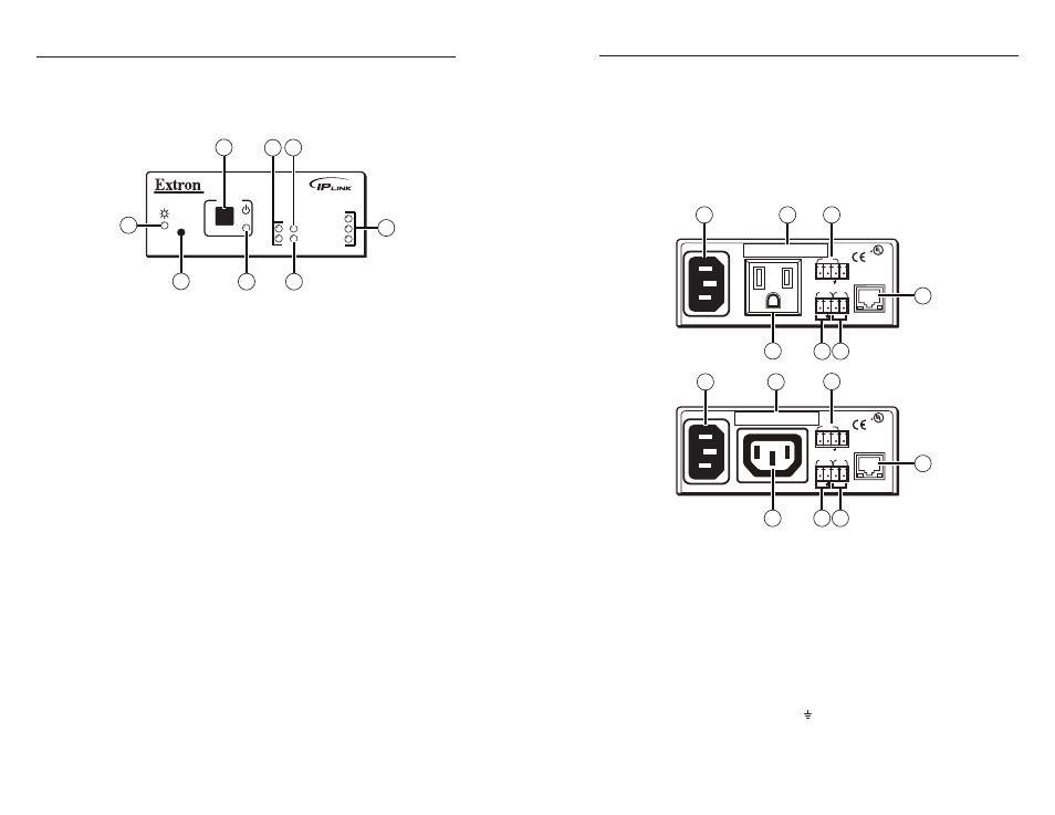
Front Panel
The front panel has a recessed Reset button, a Power button
(for the output receptacle), and the LED indicators described
below:
IPL T PC1
R
100
TX
RX
INPUT
IR
LINK
ACT
POWER
1
3
4
8
6
5
7
2
IPL T PC1 and IPL T PC1i front panel
a
Power button
— Press this button to switch power on and off
to the output receptacle on the rear panel.
b
Tx and Rx LEDs
— The Tx (transmit) LED lights green when
RS-232 data is being transmitted. The Rx LED lights green
when RS-232 data is being received.
c
Input LED
— Lights green when the Input contact closure port
is activated (shorted).
d
LAN status LEDs
— These three LEDs show the status of the
Ethernet connection as follows:
100 (green)
— When lit, indicates a 100 Mb connection
speed. Otherwise, the connection speed is 10 Mb.
Link (green)
— Indicates an active network connection.
Act (Activity) (yellow)
— Blinks while data is being sent
or received.
e
IR LED
— Lights green when IR data is being transmitted.
f
Receptacle power LED
— Indicates that power is being
supplied to the rear panel receptacle and, therefore, to the
attached output device.
g
Reset button (recessed)
— Use the tip of a small Phillips
screwdriver or an Extron Tweeker to press this recessed button
to reset the unit in one of five reset modes. (Refer to the IPL
T PC1 User's Manual
, chapter 3, "Front Panel Features and
Operation," "Resetting" section.)
•
•
•
h
Power LED
— When his green LED is lit, the PC1/PC1i
interface is receiving power and is running. When the unit is
being reset from the front panel, this LED blinks the number of
times to indicate the reset mode the PC1 has entered.
Rear Panel
The rear panel has connectors for power, control, signal input,
and signal output, and indicators as described below.
12A MAX
POWER OUTPUT 12A MAX
LAN
COM
TX
IN
S
G
+5V
RX
INPUT
IR
MAC ADDRESS
100-120VAC 50/60Hz
1
2
3
4
6
7
5
US
LISTED 17TT
AUDIO/VIDEO
APARATUS
®
10A MAX
POWER OUTPUT 10A MAX
LAN
COM
TX
IN
S
G
+5V
RX
INPUT
IR
MAC ADDRESS
200-240VAC 50/60Hz
1
2
3
4
6
7
5
US
LISTED 17TT
AUDIO/VIDEO
APARATUS
®
a
Power connector — Connect a power cord from this male IEC
receptacle to a wall outlet.
b
UID # label — Contains the unique User ID number (MAC
address) of the unit (for example, 00-05-A6-00-00-01). On the
PC1 rear panel, the MAC address is on a label directly above the
output power receptacle.
c
COM port (RS-232) — Connect the output device serial port
to this captive screw connector to enable bidirectional RS-232
device control. This serial port contains the following four pins,
in order from left to right on the rear panel: transmission (TX),
receiving (RX), ground ( ), and +5 V (to tie hand-shaking lines
on the controlled device if needed).