Wiring for ir control, Wiring the contact input port, Software setup – Extron Electronics IPL T PC1i Setup Guide User Manual
Page 12: Chapter three • software setup, Chapter three
IPL T PC1 Interface • Hardware Setup
Hardware Setup, cont’d
2-8
IPL T PC1
3
Chapter Three
Software Setup
Creating.a.Global.Configurator.Project.File
Building.and.Uploading.a.GC.File
Launching.the.GlobalViewer.Interface
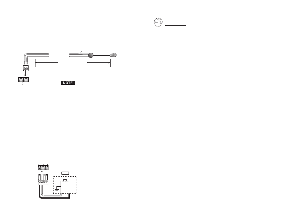
Wiring for IR control
If you intend to control the display device via infrared (IR)
commands from the PC1, you can connect an Extron IR Emitter
to the IR Signal and Ground pins (pins 3 and 4) of the shared
captive screw connector. The PC1 provides enough current to
power one IR Emitter up to 4000 feet, or up to four Emitters for
100 feet each. See the wiring illustration below.
IPL T PC1 Shared IR
and Input Connector
IR
Emitter
White striped wire only
Modulated IR
Ground
4000 feet (1574.8 m) maximum
Place the head of the IR Emitter
over or directly adjacent to the
controlled device’s IR receiver.
The PC1 can power a single IR Emitter
up to 4000 feet, or four emitters wired
in parallel up to 100 feet each.
D
E
In
S G
Wiring the contact Input port
The IPL T PC1 contact closure Input port can be connected to
any device providing a closure to ground. The contact closure
input is connected to 5 VDC via a 1k ohm pull-up resistor, and
must be wired with a ground. This allows the input to be tied
to a device such as a momentary switch, motion detector, alarm,
photo eye, etc. You can define what this input will trigger via
GC2.3.
1
.
Connect one end of the input cable to a 3.5 mm, 5-pole
captive screw connector, wired appropriately, and plug it
into pins 1 and 2 of the shared input/IR port connector on
the rear panel.
2
.
Connect the other end of the input cable to the input
device that will provide a triggering signal. (See the
diagram below.)
IN
S G
Momentary
Switch
INPUT
IR