Connecting the hardware, Wiring the local area network (lan) port, Wiring the local area network (lan) port -5 – Extron Electronics IPL T PC1i Setup Guide User Manual
Page 10: Hardware setup, cont’d
IPL T PC1 Interface • Hardware Setup
Hardware Setup, cont’d
2-4
IPL T PC1 Interface • Hardware Setup
2-5
d
LAN connector and LEDs — An Ethernet connection can be
used on an ongoing basis to monitor and control the PC1 (and
the output device connected to it).
RJ-45 port
— Plug a patch cable into
this RJ-45 female socket, and connect
the other end to a network switch,
hub, router, or PC. (See "Wiring the
Local Area Network (LAN) port,"
on the next page, for information on
cable types to use.)
Link LED
— This green LED lights
to indicate a good network connection.
Activity LED
— This yellow LED blinks to indicate
network activity.
e
IR port — Connect an IR emitter to pins 3 (S, for signal) and
4 (G, for ground) of this shared captive screw connector to
enable infrared remote control of the output device. To enable
IR control, you must load an Extron IR driver for your output
device to the PC1 (via Global Configurator).
f
Contact closure Input port
— Connect a contact closure device
to pins 1 (IN, for input) and 2 ( , for ground) of this shared
captive screw connector to enable the PC1 to detect a closed
circuit between an input and ground.
g
Output power receptacle — Connect the power cord from an
output device to this three-prong female Edison (IPL T PC1) or
IEC (IPL T PC1i) power output receptacle.
Connecting the Hardware
Connect the cables to the rear panel as follows:
1
.
Connect an IEC power cord from the PC1 rear panel male
IEC receptacle to a wall outlet. The green Power LED
lights and remains lit.
2
.
Plug the Ethernet cable from your network into the LAN
port on the rear panel. The Link LED lights green.
3
.
Plug the power cord of the device to be controlled into the
output receptacle on the back panel of the PC1.
4
.
If desired, connect the output device to the RS-232 COM
port.
5
.
If desired, connect an IR emitter to the IR port to control an
output device.
6
.
If desired, connect a contact switch to the contact closure
input port.
•
•
•
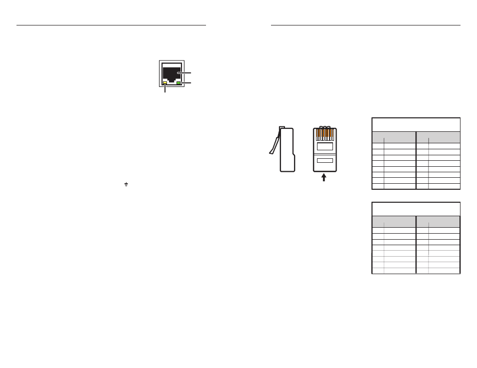
Wiring the Local Area Network (LAN) port
For 10Base-T (10 Mbps) networks, use a Category 3 or
better cable.
For 100Base-T (100 Mbps) networks, use a Category 5
cable.
Use a straight-through cable to connect to a switch, hub, or
router.
Use a crossover cable to connect directly to a computer.
Wire the connector as shown in the tables below.
Pinouts for the two types of Ethernet cables are shown in the
illustration below.
12345678
RJ-45 Connector
Insert
Twisted
Pair Wires
Pins:
Side View
Straight-through Cable
(for connection to a switch, hub, or router)
End 1
End 2
Pin Wire Color
Pin
Wire Color
1
white-orange
1
white-orange
2
orange
2
orange
3
white-green
3
white-green
4
blue
4
blue
5
white-blue
5
white-blue
6
green
6
green
7
white-brown
7
white-brown
8
brown
8
brown
Crossover Cable
(for direct connection to a PC)
End 1
End 2
Pin Wire Color
Pin Wire Color
1
white-orange
1
white-green
2
orange
2
green
3
white-green
3
white-orange
4
blue
4
blue
5
white-blue
5
white-blue
6
green
6
orange
7
white-brown
7
white-brown
8
brown
8
brown
•
•
•
•
LAN
RJ-45
Port
Link
LED
Activity
LED