Fiber optic boards, Figure 6. fiber optic board, Figure 7. optical connections – Extron Electronics FOX Matrix 7200 User Manual
Page 19
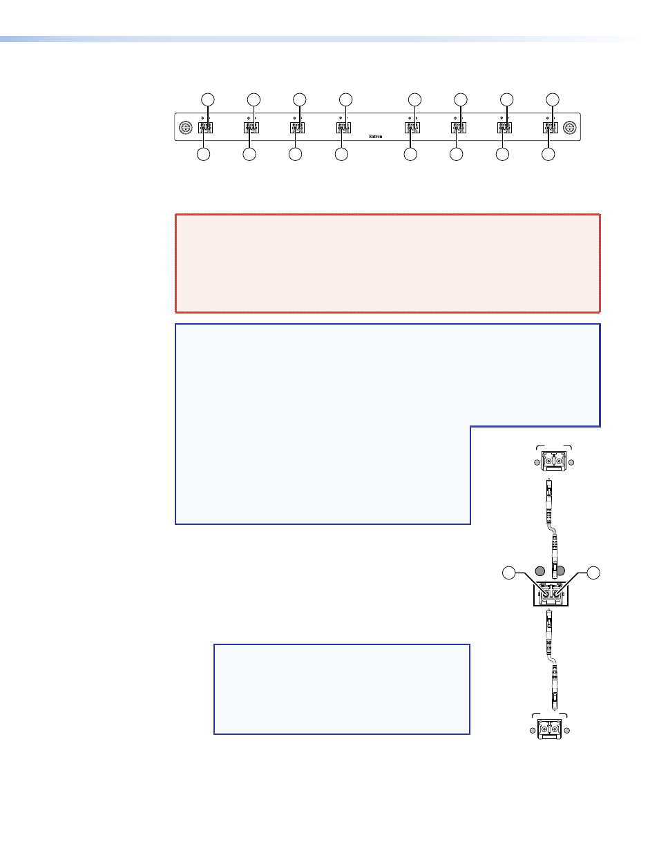
Fiber optic boards
A
B
C
D
E
F
OUT
IN
OUT
IN
OUT
IN
OUT
IN
OUT
IN
OUT
IN
G
H
OUT
IN
OUT
IN
1b
1b
1b
1b
1b
1b
1b
1b
1a
1a
1a
1a
1a
1a
1a
1a
Figure 6.
Fiber Optic Board
a
Fiber optic board, connectors (see
on page 8 and
on page 9) —
WARNING: Risk of serious physical injury — The FOX matrix switchers fiber optic
I/O boards output continuous invisible light, which may be harmful to the eyes; use
with caution.
•
Do not look into the fiber optic cable connectors or into the fiber optic cables.
•
Plug the attached dust caps into the optical transceivers when the fiber cable is
unplugged.
NOTES:
•
Ensure that you use the proper fiber cable for your I/O board. Typically, singlemode
fiber has a yellow jacket and multimode cable has an orange or aqua jacket.
•
Unlike most Extron transmitters and receivers, which output an optical stream on one
connector in a block and receive a return optical stream on the second connector
in the same block, the FOX matrix switchers uses one connector on the block as an
input and the second connector on the same block as a separate output.
•
All transceiver modules on a fiber optic I/O board, as
delivered from Extron, are configured the same: either
all multimode or all singlemode.
•
You can mix multimode and singlemode fiber optic I/O
boards in a FOX matrix switcher, but you must ensure
that you connect the proper transmission mode fiber
cables to the board.
Ä
Input connector and LED — For all one‑way
video, audio, and serial communications output by a
transmitter, connect a fiber optic cable to the Input LC
connector (see figure 7).
Connect the free end of this fiber optic cable to the
Optical Tx LC connector on a FOXBOX Tx transmitter
or to any other compatible fiber optic device.
NOTES:
•
For a FOX 500 transmitter, connect this fiber
optic cable to the Optical 1 LC connector.
•
Alternatively, for the serial return, (receiver‑to‑
transmitter) function, connect the far end of the
cable to the Optical 2 connector on a receiver.
Input LED — See
OUT
IN
Extron
Fiber Optic
Transmitter
Extron
Fiber Optic
Receiver
FOX
Matrix
Switcher
OPTICAL
LINK
LINK
Rx
Tx
Rx is optional
connection
Tx is optional
connection
LINK
LINK
Rx
Tx
1b
1a
Figure 7.
Optical
Connections
FOX Matrix 3200 and 7200 Switchers • Installation
11